
Smarter by Design.Simpler for Business
Add IP Address (Cluster)
What Is Add IP Address?
Add IP Address is a fundamental configuration operation that provides network connectivity and service accessibility by assigning IPv4 or IPv6 addresses to the interfaces on the TR7 device. On TR7 the IP addresses define the listening points at which the vServices will accept the traffic coming from the clients.
While a vService is being created, the IP address and the port over which the service will be accessible are determined; for this reason the IP address configuration is the first step of traffic management. Every IP address is bound to a specific interface and route table; in this way the traffic coming from different network segments is routed according to the rules of the related route table. By adding more than one IP address to the same interface, more than one service can be run on a single physical or logical interface.
TR7 supports both IPv4 and IPv6 addresses; when an IP address is entered, the system detects the address format automatically and configures the appropriate protocol.
IPv4 + IPv6
Dual-stack
Both protocols can be added to the same interface in parallel
Multiple IPs
Per interface
More than one service/IP on a single interface
Route Table
Traffic isolation
Every IP is subject to the rules of a route table
VIP
Listening address with failover
It runs on the Master device and passes to the Slave in a failure
Cluster / Standalone
This page describes the IP adding form used while clustering (cluster) is enabled. All the fields of the standalone form are valid here as well; the cluster form extends it with the VIP option in the Ip type field, the peer device address column in the Interface IPs and the IP status per device. For the standalone version see the Interfaces (Standalone) page.
The IP Types in Cluster Mode
In cluster mode two different IP types are supported: Interface IP and VIP (Virtual IP). The two serve different purposes and their correct use is critical for high availability.
Interface IP Does not transition
It is the fixed IP address specific to every TR7 device; it does not pass between the devices in a failover, every device keeps its own address. It is used for device management and for the VRRP communication of the VIPs; an Interface IP pair whose address is defined for both devices makes the VIPs work by being selected in the VIP communication field of the interface.
VIP (Virtual IP) Otomatik failover
It is the virtual IP address that can make an automatic failover between the cluster devices. The vServices serve over the VIP. When the active device (Master) goes out of service, the VIP passes automatically to the passive device (Slave) and the service continues from the peer device with a short interruption.
The Cluster IP Structure
VIP ·
10.0.1.100The vService listening address Failover
TR7 #1MASTER
Interface IP: 10.0.1.1VRRP
TR7 #2SLAVE
Interface IP: 10.0.1.2The MASTER / SLAVE role in the diagram belongs not to the device but to the VIP: the Master device is selected separately for every VIP; different VIPs on the same interface can be Master on different devices.
| IP Type | Failover | Purpose of Use |
|---|---|---|
| Interface IP | Does not transition | Device management, VIP communication (VRRP) |
| VIP | Automatic transition | The vService listening address, client access |
TIP
The vServices that require high availability must be published over a VIP in cluster mode; in this way, in case of a failover the service continues from the peer device with a short interruption.
An Interface IP can be used in a vService as well
Interface IP addresses can also be selected as a listening address in a vService. However, since an Interface IP does not pass between the devices in a failover, a vService published over this address becomes accessible only on the related device and does not provide high availability. For this reason a VIP is preferred in the services that require HA, and an Interface IP in device-local services.
Why Is Add IP Address Important?
IP addresses are the fundamental building blocks of network communication. On TR7 a correct IP configuration is of critical importance in terms of service accessibility, traffic routing and network security.
- vService Accessibility: Every vService accepts client requests over a specific IP address and port combination. A vService cannot be run on an interface to which no IP address has been assigned.
- Multiple Service Support: By adding more than one IP address to a single interface, different IP addresses can be used for different services over the same physical connection. It is especially important in the scenarios that require the IP-based separation of SSL/TLS certificates.
- Route Table Integration: IP addresses work integrated with the route table structure. The IP addresses assigned to the interfaces in different route tables are subject to the routing rules of the related table; in this way traffic isolation and segmentation are provided.
- IPv6 Transition: A dual-stack (IPv4 + IPv6) configuration is supported. Both IPv4 and IPv6 addresses can be added to the same interface; this provides flexibility during the IPv6 transition process.
The Profile-Based IP Model
In TR7 the IP addresses are permanent network resources that live at the device/configuration level. An IP address is defined bound to an interface and to a route table; the vServices, on the other hand, only use this IP as a listening address. That is, the IP exists at the network layer first; the vService references this address afterwards.
This separation separates TR7 fundamentally from the traditional approaches in which the IP is embedded in a service object:
TR7: The Profile-Based IP The network layer
The IP address is first defined on the interface and is part of the device configuration. The vServices use this address as a listening point; however, the life cycle of the IP is completely independent of the vService.
The Traditional Approach: VIP-Based The service object
In traditional ADCs/load balancers the IP (VIP) is entered while the service object is being created and is usually handled together with that object; the address behaves like a property of the related service object.
Important: IPs live independently of the vService
Even if an IP address is removed from a vService or that vService is deleted completely, the IP address stays defined and active on TR7 as long as it is not deleted or disabled: it is bound to the interface and continues to respond at the network layer (ARP/access). This makes it possible for the IP to be reused in another vService; however, in order to prevent unexpected IP collisions, the addresses that are no longer used need to be cleaned up.
In order to remove an IP address completely, the Delete IP operation of the related IP on the Interfaces List screen, and in order to disable it temporarily, the Disable for [Hostname] operation is used.
Best Practices
- Assign the IP addresses in a planned way. Instead of assigning them randomly, plan the IP blocks according to the service type or the purpose of use (e.g.
10.0.1.xfor web services,10.0.2.xfor API services). - Use the Disabled option in migration scenarios. While migrating from a different device to TR7, add the IP addresses as Disabled first; in this way there is no collision with the IP on the source device. When the migration is completed, the IP on the source device is deleted and it is enabled on TR7 with Enable for [Hostname].
- Determine the subnet mask (CIDR) value correctly. While adding an IP address, make sure that the CIDR notation is suitable for the network topology; a wrong subnet mask leads to routing and accessibility problems.
- Pay attention to the route table selection. The selected route table determines which routing rules the traffic will be subject to; a wrong selection may cause the traffic to be routed unexpectedly.
- Configure the IPv6 addresses in parallel. In preparation for the IPv6 transition, assign both IPv4 and IPv6 addresses to the interfaces whenever possible; this dual-stack configuration makes the future transition easier.
How to Add?
There is more than one way of adding a new IP address on the TR7 device. The first three methods open the same Add IP Address Form as a closable tab inside the interface list screen:
From the Actions Menu Method 1
The Configuration Menu is opened with the TR7 logo and the Network → Interfaces → Actions → Add IP steps are followed. In the form the first interface of the list comes selected; the correct interface must be selected in the form.
From the Preview Panel Method 2
On the Network → Interfaces screen an interface is selected; in the preview panel that opens on the right the IP tab is opened and the Add IP button is clicked. The selected interface comes ready in the form (if the Route table filter on the list screen is set to a different table, the first interface of that table is selected instead).
From the Right-Click Menu Method 3
On the Network → Interfaces screen an interface is right-clicked; Add IP is selected from the menu that opens. The selected interface comes ready in the form (if the Route table filter on the list screen is set to a different table, the first interface of that table is selected instead). On the interfaces that are Bond/LACP members this option is passive.
From the vService Form Method 4
While a vService is being created or edited, the Add IP operation in the IP selection list opens the same form as a window (modal); the IPs added come directly into the IP list of the vService. This operation is offered only to the users who have network configuration authorization.
Besides, the Add IP button on the Dashboard screen of an interface also opens the same form with the interface selected.
WARNING
While a network operation continues (while the "Network is under action. Please wait..." warning is seen), the Add IP in the right-click menu becomes passive; the Add IP in the Actions menu, on the other hand, stays open. A record sent during this time is rejected with the "Configuration sync in progress. Please try again later." error; the operation must be waited to finish and the record must be tried again.
The Add IP Address Form
By following one of the methods above, the IP address adding form is opened. There is no Details section in the form; the fields are explained below in screen order. According to the Ip type selection the columns of the IP table change.
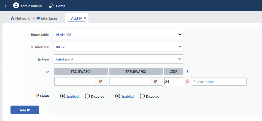 The IP Address Adding Form (Interface IP)
INFO
Route Table
A route table is selected in order to narrow the IP interface list; this field is seen only if more than one route table is defined. If a specific table is selected in the Route table filter on the interface list screen, that table comes ready; if the filter is in the All route tables position, the table of the interface from which the form is opened comes ready. The field is only for filtering; the route table of the IP is the table of the selected interface. For the details see the Route Tables page.
INFO
IP Interface
The interface to which the IP address will be added is selected; all the interfaces in the selected route table are listed and the interfaces that are bond/LACP members are passive. If the form has been opened from a specific interface, the related interface comes selected but can be changed; when it is opened from the Actions menu or while the Route table filter is set to another table, the first interface of the list comes selected. Before the record it must be checked that the correct interface is selected. If an interface that is a bond/LACP member is selected, the "... is a bond/LACP member" warning is given and the form cannot be submitted.
INFO
IP Type
The type of the IP address (Ip type) is selected; the default is Interface IP:
- Interface IP: an address pair specific to every device: the address of this device and the address of the peer device are entered separately. It is used for device management and for the VRRP communication of the VIPs; it can be selected as a listening address in a vService but it does not transition in a failover.
- VIP: a virtual address shared between the two devices, running on the Master device and passing to the Slave device in a failure. It is used as the high-availability listening address of the vServices.
WARNING
When Ip type is changed in the adding form, all the rows in the IP table are cleared and an empty row suitable for the new type comes.
INFO
IP
The IP addresses to be added are entered as a table; the columns of the table change according to the selected Ip type.
While Interface IP is selected there are three columns: the machine name of this device, the machine name of the peer device and CIDR. In every row:
- The address of this device: the IPv4/IPv6 address to be used on this device (e.g.
10.0.1.1); the badge next to the box shows the version of the address (IPv4 / IPv6). - The address of the peer device: the address of the same IP record on the peer device (e.g.
10.0.1.2). It can be left empty; in this case no address is defined on the peer device. When both addresses are entered, they must be in the same IP version and in the same subnet as the CIDR entered; otherwise the record is rejected with the "Different Ip versions (...)" or "Subnet error" error. - CIDR: the prefix length; the default is 24. It must be in the
0–32range for IPv4 and in the0–128range for IPv6. - IP description: an optional description is entered in the box on the right of the row; the description is displayed in the tooltip of the IP and, when it is opened from the Columns window, in the IP description column of the interface list, which is hidden by default.
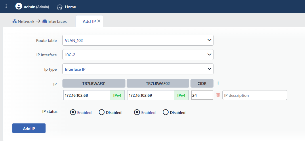 The Interface IP Row Filled In
While VIP is selected there are three columns (IP, Master/slave and CIDR). In every row:
- IP: the virtual address to be shared between the two devices; a single address is entered.
- Master/slave: on which device the VIP will normally run: Master (the default) is this device, Slave the peer device. In the list the Master side is shown with the (M) suffix and the Slave side with the (S) suffix.
- CIDR: the box comes as
auto; when it is left empty,/32is assigned for IPv4 and/128for IPv6, and a value entered is used as it is (entering0counts as empty).
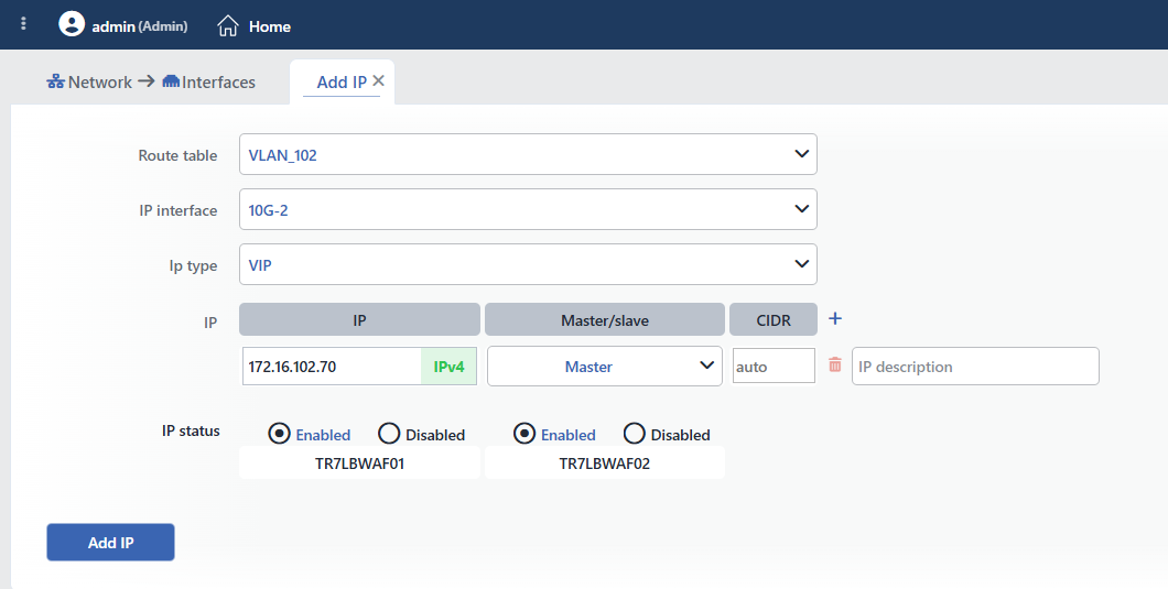 The IP Table While VIP Is Selected
Adding Multiple IPs
By clicking the + icon in the CIDR header, new rows are added to the table; all the addresses are assigned to the same interface. The rows are removed with the trash can icon, but the last row cannot be deleted.
WARNING
The form does not validate the addresses before they are sent; a row both of whose addresses are left empty (if only the peer device address is entered, the record is accepted and the address is defined on the peer device only), an invalid address, a CIDR outside the range or an address already defined in the same route table is rejected during the record by the server with the "IP not given", "Invalid IP: ...", "Invalid CIDR: ..." or "IP collision: ..." error; when an attempt is made to add an IP to the cluster synchronization interface, the "Interface '...' is protected (...)" error is returned. In this case the form stays open and the values entered are preserved.
INFO
IP Status
In the IP status row below the table there is an Enabled / Disabled selection for every device separately (the default is Enabled for both); the selection is applied to all the addresses added:
- Enabled: the address is added as active on the related device; it becomes accessible as soon as the configuration is applied.
- Disabled: the address is defined on the related device but is not applied to the system; it is shown gray and struck through in the column of that device in the interface list. It is used in order to keep a device away from the traffic in migration or maintenance scenarios; the address is enabled later from the interface list with the Enable for [Device name] operation.
In the VIP rows the names of the related devices are displayed below the two selections (see the VIP image above); if a VIP is disabled on a single device only, the Disabled status is shown for that device in the list.
INFO
Add IP
The IP addresses are saved by clicking the Add IP button. The adding does not ask for confirmation; the record returns immediately, the system application starts in the background (if necessary the interface is turned on automatically) and the form tab closes. The addresses added are displayed as sub-rows in the two device columns in the row of the related interface on the Interfaces List screen. The Interface IPs are listed in every column with their own address and with the device-based status:
Absent in system · redThe record has been taken but the configuration has not been applied to the system yet; the address appears red for a short time.
Up · greenThe configuration has been applied to the system; an address added as Enabled appears green and is usable.
Disabled · light gray, struck throughAn address added as Disabled is not applied to the system; it is shown dimmed and struck through.
In the list the status color is applied to the text of the IP address; the color tones may change according to the selected theme. When the interface itself is down or has no link, the address inherits the status of the interface (Down, No link, etc.); if the peer device cannot be reached, the peer column shows Host is down in the Interface IPs (in the VIPs this situation is expressed with the VIP statuses below).
The VIPs, on the other hand, are listed in both columns with the same address and with the (M) / (S) suffix; their colors reflect the VIP status of the two devices evaluated together; the expected stable state is Master VIP is active (green) on the Master side and Slave VIP (light gray) on the Slave side; in a failover Slave VIP is active, in a collision Both VIP is active (red). For all the VIP statuses see the Interfaces List › The VIP Statuses section.
The precondition for the VIP to become active
A VIP does not become active without there being an Interface IP pair whose address is defined for both devices on the interface it is bound to and without this pair being selected as the VIP communication (VIP communication (v6) for an IPv6 VIP) in the Edit Interface form. No warning is given about this during the adding; the "The VIP will NOT be active until interface '...' has a VIP communication pair and router ID" warning is displayed only while the type of an existing IP is being turned into a VIP. The recommended order: first the Interface IP pair, then the VIP communication in Edit Interface, and the VIP last. If the VIP is added first, it stays passive until the pair is selected and becomes active automatically when the pair is selected.
Editing an IP Address (Edit IP)
An existing IP address is edited on the Interfaces List screen by right-clicking the IP or by selecting it in the IP tab of the preview panel and using the Edit IP operation. The editing form has the same structure as the adding form; its differences are as follows:
- The Route table and IP interface fields are locked; an IP cannot be moved to another interface.
- In the IP table there is only the row of the address being edited; a row cannot be added or deleted.
- Ip type can be changed in the editing as well (Interface IP ↔ VIP); the row is rearranged according to the columns of the new type.
- The button of the form becomes
Edit IP. A change of the address, the CIDR or the description is saved without confirmation being asked; in a change of Ip type, on the other hand, an "Are you sure?" confirmation that lists the effects opens and, if there is an effect at the 🔴 level, a second "This action has destructive consequences. Are you REALLY sure?" confirmation is asked as well:
| Direction | Level | Warning | Meaning |
|---|---|---|---|
| → VIP | 🔴 | "This IP is the VIP communication pair of interface '...' — its entire VIP configuration will be torn down" | The address is being turned into a VIP while it is the VIP communication pair of the interface; the VIP configuration of the interface is broken |
| → VIP | 🔴 | "The VIP will NOT be active until interface '...' has a VIP communication pair and router ID" | There is no VIP communication pair on the interface; the VIP will not become active |
| → VIP | 🟠 | "The peer-node address ... will be removed" | Since the peer device address is not used in a VIP, it will be deleted |
| → VIP | 🟠 | "... is a management access IP — as a VIP it will only be reachable on the active node" | When a management access IP becomes a VIP, it is accessible only from the active device |
| → Interface IP | 🟠 | "... leaves VIP management and becomes a static address on '...' (VIP config will be regenerated)" | The VIP is turning into a fixed address |
| → Interface IP | 🟠 | "No peer-node address given — the other node will have no address for ..." | The peer device address has not been entered |
IP deletion and protected addresses
- An IP defined in the management access lists (HTTP, HTTPS, SSH, SNMP) of the device cannot be deleted and cannot be disabled with the Disable for [Hostname] operation in the interface list; the operation is rejected with the "${ip} is protected. (${reason})" error. This protection is not applied to the IP status selection in the Edit IP form: making an access IP Disabled from the editing form may lead to management access to the device being cut off.
- The IP deletion operation opens a confirmation window; however, no separate warning is given for the routes and the default gateway reached over the IP; since the routes are bound to the interface, they stay in place. Before deleting an address, it must be checked that the routes in the network of that address will still be accessible.
- If the deleted Interface IP is used as the VIP communication pair of an interface, the 🟠 "The cluster IP pair of the following interfaces will be cleared: ..." warning is listed in the confirmation window; the VIPs on the related interface lose their activity.
- In order to disable an address on a single device only, the Disable for [Device name] operation in the interface list is used; the management access IPs cannot be disabled in this way.