
Smarter by Design.Simpler for Business
Backend Groups
What Is Backend Groups?
Backend Groups is the screen where Backend Groups, which gather multiple application servers offering the same service under a single logical structure, are defined. Servers with similar functions, such as web servers, application servers and API services, are defined within a group by sharing common configuration settings.
In the TR7 architecture, Backend Groups serve the same purpose as individual Backend Services: defining the target application servers to which vServices forward traffic. The basic difference is that groups contain more than one server and these servers share a common configuration.
In a Backend Group:
- Common Group-Level Settings: Configurations such as health check, SSL/TLS configuration, SNAT settings and maintenance mode are defined at the group level and automatically applied to all servers in the group.
- Individual Server-Level Settings: The IP address, port number, weight, connection limit and cookie content can be defined separately for each server. This flexibility allows servers with different capacities to be used in the same group.
What can be done with Backend Groups
- Managing dozens or hundreds of servers with a single configuration.
- Applying configuration changes to all servers from a single point.
- Adding/removing servers within seconds.
- Applying consistent health check and SSL policies on a group basis.
- Providing granular traffic control among servers with different capacities.
- Reducing operational complexity and minimizing human error.
The Importance of Backend Groups
In modern load balancer architectures, scalability and management efficiency are the cornerstones of successful operations. Backend Groups combine these two requirements and make the effective management of large-scale infrastructures possible.
Gathering multiple servers that offer the same service under a group, instead of defining them as individual Backend Services, dramatically reduces management complexity. For example, instead of configuring a separate health check profile, SSL setting or maintenance mode for each of 20 web servers, all these settings are defined once at the group level and automatically applied to the 20 servers.
Centralized Management Advantage
Configuration changes are controlled from a single point. When the SSL cipher suite needs to be updated in the production environment, a single change made at the group level is instantly reflected on all servers. This approach:
- Guarantees consistency: All servers have the same configuration, and configuration drift is prevented.
- Reduces the risk of error: Since it does not require updating each server separately by hand, it leaves no room for human error.
- Shortens the change time: The configuration of dozens of servers is updated within seconds.
Elastic Scalability
During traffic increases, capacity can be increased by adding new servers to the group. The added server automatically inherits the group's existing configuration:
- The health check profile is applied.
- The SSL/TLS connection settings become active.
- The SNAT and proxy protocol configuration takes effect.
- The server starts receiving traffic according to its weight value.
When traffic decreases, cost is optimized by removing unnecessary servers from the group. These operations take place without affecting vService traffic.
Granular Traffic Control
The server-level weight and connection limit parameters enable the precise management of capacity differences:
- While weight 4 is assigned to a server with 32 GB RAM, weight 2 can be assigned to a server with 16 GB RAM.
- A gradual warm-up can be provided by giving a newly added server a low connection limit.
- Servers with old hardware can be kept in the group with a low weight.
Health Check and Fault Tolerance
The health check defined at the group level is applied to each server separately. Failed servers are automatically taken out of traffic, but the group as a whole continues to serve. If 2 out of 10 servers in a group fail, the remaining 8 servers share the traffic. When failed servers recover, they are automatically taken back into the group.
Centralized
Management from a single point
Hundreds of servers are managed with a single configuration
Elastic
Fast scaling
Adding/removing servers within seconds
Granular
Per-server control
A separate weight and connection limit for each server
Consistent
No configuration drift
All servers share the same common configuration
With correctly configured Backend Groups:
- Hundreds of servers are managed centrally.
- Configuration changes are applied within seconds instead of minutes.
- Server failures are tolerated automatically.
- Capacity changes take place without service interruption.
Backend Group and Backend Service Comparison
The basic differences between Backend Groups and individual Backend Services are as follows:
| Feature | Backend Service | Backend Group |
|---|---|---|
| Server Count | Single server | Multiple servers |
| IP:Port | Single address | Different IP:Port per server |
| Common Settings | None | Shared at the group level |
| Weight/Limit | Single value | Different value per server |
| Management | Separately | Centralized |
| Record Count | A separate record for each server | All servers in a single record |
| Health Indicator | The service's own status | The aggregate status calculated from the servers' results (including Partially Healthy) |
INFO
When should a Backend Group be used?
- If there are multiple servers offering the same service.
- If load balancing will be performed among the servers.
- If ease of management with a common configuration is desired.
- If servers will be added/removed frequently.
INFO
When should an individual Backend Service be used?
- If there is a single server.
- In cases where the server requires a completely different configuration.
Effects and Behavior
The configurations made on Backend Groups directly affect how traffic is distributed and how the servers in the group behave. The interaction of group-level and server-level configurations provides the flexibility of traffic management.
INFO
Health Check
The health check profile defined at the group level is applied to each server in the group separately. TR7 sends check requests to each server at the specified intervals. Servers whose check fails are taken out of traffic individually, but the group as a whole continues to serve. Healthy servers share the load of the failed server. The group indicator on the listing screen is an aggregate value calculated from the servers' results: if the statuses of the servers differ from each other, the group is marked as Partially Healthy. When the failed server becomes healthy again (when the number of consecutive successes reaches the Required Successes threshold in the profile), it is automatically taken back into the group and starts receiving traffic. The thresholds, check interval and timeout come from the selected Health Checks profile.
INFO
Backup Service
When the group is marked as a backup service, all servers in the group are included in the backup services. Backup groups come into play only when all other main (non-backup) Backend Services and groups bound to the same vService are unavailable. Under normal conditions, no traffic is directed to backup groups. When the main services become healthy again, the traffic automatically returns to the main services. Even when backups come into play, only the first available backup server receives traffic at a time; the traffic is not distributed among the backup servers.
INFO
SSL Service
When the SSL service is enabled at the group level, TR7 establishes an SSL/TLS connection to each server in the group. The cipher suite, SNI (Server Name Indication) and ALPN (Application-Layer Protocol Negotiation) settings are defined at the group level and applied to all servers. All servers in the group must support the same SSL/TLS configuration. By default (Certificate Verification: None), since the server certificate is not verified, self-signed certificates or certificates signed by an internal CA work without problems; if verification is needed, it can be made mandatory through a CA profile with the Required option.
INFO
Maintenance Mode
When maintenance mode is enabled, no traffic is directed to any server in the group. Regardless of the health check status, the whole group is taken out of traffic collectively. While the change is applied, the existing active connections are not cut; they are left to complete, and no new connections are sent to the servers. This feature is used for simultaneous group-wide maintenance or deployment operations. When maintenance mode is disabled, health checks start again and the servers that succeed are included in traffic.
INFO
Server-Level Weights
The weight of each server is determined independently. The load balancing algorithm of the vService (weighted round-robin, least connection, etc.) distributes traffic by taking the server weights into account. The total traffic is distributed to the servers according to the ratio of the weights. For example, if the weights in a 3-server group are 1, 2 and 4, 14%, 29% and 57% of the total traffic, respectively, is directed to these servers. The weight value is in the range 1–256; if a distribution algorithm that ignores weights is selected in the vService, these values are not applied.
Operational Best Practices
The following best practices should be taken into account when configuring Backend Groups.
- Logical and homogeneous grouping should be done. Servers that offer the same service and require similar configuration should be gathered under a group; different services or servers that require different configurations should not be mixed in the same group. It is ideal for all servers in the group to run the same application version, have the same SSL/TLS capabilities and offer the same health check endpoint.
- Descriptive and consistent naming should be used. The service type, version, environment and geographic location should be indicated in group names; a consistent naming standard should be determined and applied to all groups. Recommended format:
{service}-{version}-{environment}-{region}. Meaningless names such asgroup1,servers,backendandtest-groupshould be avoided. - Weights should be set in proportion to hardware capacity. If servers with different hardware capacities are used in the same group, the weight values should be set in proportion to the number of CPU cores, the amount of RAM or the disk I/O capacity; powerful servers should receive more load according to their capacity.
- Connection limits should be evaluated realistically. A
Connection Limitsuited to the capacity of each server should be defined; the limit should be determined according to the server's thread/worker pool, memory usage and application architecture. A limit that is too high leads to overload and performance degradation, and a limit that is too low leads to capacity not being fully used. - Health check profiles should be standardized. Common health check profiles should be created and shared for groups of the same type; this approach increases consistency and simplifies management. Separate profiles should be created for groups with different check requirements (different timeout, health endpoint, expected response), but standardization should be preserved as much as possible.
- Groups should be used for future scaling. Even if there is a single server at the moment, creating a group should be considered if there is a scaling plan for the future; adding servers later becomes as simple as entering an IP:Port, configuration changes are simplified and the architecture gains consistency.
- Meaningful Cookie Content should be used for cookie persistence. If cookie-based persistence is used, meaningful and unique cookie values should be defined for each server (not
server1,server2butweb-prod-01,api-node-02); this makes it easier to understand during troubleshooting which server a request was directed to by looking at the cookie value on the client side.
The expandable sections below contain concrete examples and calculations for each best practice.
Logical and homogeneous grouping: correct and incorrect examples
Correct examples:
web-frontend-prodgroup → 10 web servers, Apache 2.4, HTTP/HTTPSapi-v2-backendgroup → 5 API servers, Node.js 18, JSON APIdatabase-read-replicasgroup → 3 MySQL read replicas
Incorrect examples:
- Both web servers and API servers in the same group
- Different application versions (v1 and v2) being in the same group
- Mixing HTTP and FTP servers
Descriptive and consistent naming: examples
The service type, version, environment and geographic location are indicated in group names. Recommended format: {service}-{version}-{environment}-{region}
Good examples:
web-frontend-prod-euapi-v2-staging-us-eastcache-redis-prod-primarydb-mysql-read-prod
Bad examples: group1, servers, backend, test-group
Setting weights in proportion to hardware capacity: example
If servers with different hardware capacities are used in the same group, the weight values are set in proportion to the number of CPU cores, the amount of RAM or the disk I/O capacity.
When there are three different servers in a group:
- Server-A: 32 vCPU, 64 GB RAM → Weight: 8
- Server-B: 16 vCPU, 32 GB RAM → Weight: 4
- Server-C: 8 vCPU, 16 GB RAM → Weight: 2
In this case, the traffic is distributed at the ratios of 57%, 29% and 14%; more powerful servers receive more load according to their capacity.
Evaluating connection limits realistically: calculation example
A Connection Limit suited to the capacity of each server is defined. The limit should be determined according to the server's thread/worker pool, memory usage and application architecture.
Calculation example: If a Node.js application handles 1000 connections per worker and 4 workers are running, the connection limit can be set to 4000. Using 3200, leaving a 20% safety margin, is recommended.
Setting the limit too high leads to server overload and performance degradation, and setting it too low leads to capacity not being fully used.
Standardizing health check profiles: example profiles
Common health check profiles are created and shared for groups of the same type.
Example standard profiles:
HTTP-80-Standard→ for all HTTP web server groupsHTTPS-443-API→ for all HTTPS API groupsMySQL-3306-Check→ for all MySQL backend groups
Separate profiles are created for groups with different check requirements (different timeout, different health endpoint, different expected response); however, standardization is preserved as much as possible.
Using groups for future scaling: scenario
Even if there is a single server at the moment, using a Backend Group is considered if there is a scaling plan for the future. Creating a group:
- Makes it easier to add servers in the future (adding a single row).
- Simplifies configuration changes.
- Brings consistency to the architecture.
Scenario: There is a single API server for a pilot project; if the load increases, the number of servers will be raised to 5. When the group is created from the start, adding new servers becomes as simple as entering an IP:Port.
How to Add?
A new Backend Group is added through the TR7 web management interface with the following steps:
- The Configuration Menu is opened by clicking the TR7 logo at the bottom left.
- The Load Balancer → Backend Groups → Add steps are followed.
- A unique and descriptive name is entered for the Backend Group.
- In the Backends table, a row is created for each server to be added to the group, and the IP address and port information are entered; the other required settings are configured.
- The Backend Group is added by clicking the
Addbutton.
TIP
Reaching the page via quick search
Instead of navigating the menu step by step, the related page is reached directly by using the search bar in the bottom left corner of the screen. The search bar opens with the Alt + T shortcut on Windows and Opt + T on macOS; typing the name of the feature being searched for is then sufficient.
The created Backend Group is used by adding it to the Default Backend Services or Conditional Backend Services list of vServices (Usage Location).
Backend Groups Listing Screen
The list of all Backend Groups defined on the TR7 device is reached by following the Load Balancer → Backend Groups path. Adding, editing and deleting Backend Groups are performed on this screen.
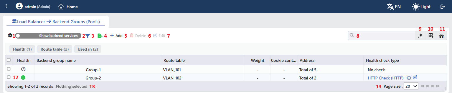 Backend Groups Listing Form
The table opens with the following columns by default:
| Column | Description |
|---|---|
| Health | The aggregate health check status of the group is shown with a colored circle (described under Health Status Indicator). |
| Backend Group Name | The name of the group; next to it, if the related setting is on, there are the SSL (lock), maintenance mode (ambulance) and backup service icons, in order. |
| Route Table | The route table the group is bound to. |
| Weight | Since the weight is per server, - is shown in the group row; while Show Backend Services is on, the weight of each server is displayed in a separate row. |
| Cookie Content | Since the cookie content is per server, - is shown in the group row; while Show Backend Services is on, the value of each server is displayed in a separate row. |
| Address | The number of servers in the group, in the Total of N format; while Show Backend Services is on, the IP : port information of each server is displayed in a separate row. |
| Health Check Type | The health check profile assigned to the group in the profile name (Type) format; No Check if no profile is assigned. The profile summary opens with the info icon next to the profile name, and the profile opens in an edit window with the pencil icon. |
| vDevice | The vDevice on which the group is defined. This column does not exist in virtual machine setups. |
There is no column hidden by default. When a column header is clicked, descending sorting is applied first, then ascending; on the third click, the sorting is removed.
The items in the toolbar are arranged from left to right in the following order; item 12 is the indicator in the table cell, and the last two items (Page Information and Page Size) are located in the information strip below the table.
Columns
Which columns are shown in the table is selected; all columns are on by default. In the same panel, columns are reordered by dragging and alignment (Align Left, Center, Align Right) is selected per column; the row height is fitted to the page with the Fit rows to the page button, and the column layout is reset to default with the Reset button. The layout is stored per user.
WARNING
The column layout is shared with the Backend Services screen; a column hidden or reordered here also changes on the other screen.
Show Backend Services
When the Show Backend Services switch above the table is turned on, each group row is split into as many sub-rows as the number of servers in the group: the Health, Weight, Cookie Content and Address columns show the per-server values separately; Backend Group Name, Route Table, Health Check Type and vDevice stay as a single cell for the group. While the switch is off, each group is a single row and the Total of N summary appears in the Address column.
The switch is off by default; its position is stored per user.
Filter
The Filter button is used to filter the Backend Groups shown in the list according to specific criteria; the button shows the number of active filters with a badge. The filter strip is open by default and contains three cards:
| Card | Values |
|---|---|
| Health | The health check profiles assigned to groups (profile name (Type)). Groups with no health check assigned are not included in the values of this card. |
| Route Table | The route tables the groups are bound to. |
| Used in | The vServices that use groups, and the Unused Entries value that lists the groups not used anywhere. |
The card header contains the filter name and the number of values; when a card is clicked, the values are listed below it with their row counts.
Export
The table is exported as Excel, CSV or PDF by clicking the Export button. In the window that opens, the Filename, Format and Data Source, together with the Columns to be exported, are determined; the remaining fields are displayed according to the format: CSV Separator for CSV, Excel Sheet Name for Excel, and Page Orientation and Page Size for PDF.
Add
By clicking the Add button, the form for creating a new Backend Group opens in the Add tab.
Delete
When one or more Backend Groups are selected and the Delete button is clicked, the related groups are deleted. Before deletion, the confirmation "Are you sure that you want to delete backend service object?" is requested for a single selection and "Are you sure you want to delete N backend service objects?" for a multiple selection. The button is inactive when there is no selection.
WARNING
A Backend Group used in a vService is also deleted; the deletion is not blocked because of usage. The deleted group is removed from the Default Backend Services and Conditional Backend Services lists of the vServices it is bound to, and all servers in the group stay out of traffic. The Used in tab in the preview should be checked before deletion. A Log record is written for each deleted group.
Edit
By clicking the Edit button, the edit form of the selected Backend Group opens in the Edit tab. The button becomes active only when a single group is selected.
Search
Used to search all information in the table.
RegExp Search
Used to search all information in the table with a regular expression (RegExp).
Column Based Search
Used to perform a column-based search on the information in the table.
Usage Filter
Used to filter which vServices the Backend Groups are bound to. When the button is turned on, the search box turns into a vService selector and the first option is selected automatically; the selector contains the vServices that use at least one group and, at the bottom, Unused Entries. When a vService is selected, only the groups used in that vService are listed; when Unused Entries is selected, the groups not used anywhere are listed.
Health Status Indicator
The indicator in the Health column reports the health check status of the group with a color; when the pointer is over the indicator, the name of the status is displayed. The group's health check profile is applied to each server separately, and the group indicator is an aggregate value calculated from the servers' results: if all servers are in the same status, that status is shown; if the statuses of the servers differ from each other, Partially Healthy is shown.
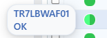 Health Check Status
| Indicator | Status | Description |
|---|---|---|
| ● Green | OK | All servers in the group are up according to the health check. |
| ● Red | Error | All servers in the group are down according to the health check. |
| ● Orange | Partially Healthy / Preparing | The statuses of the servers differ from each other (e.g. one is OK, another is Error or Preparing); or the check result is not yet final on all servers. |
| ● Gray | HC Disabled / No Data | There is no health check result, no data has arrived yet, or no server is defined in the group. |
| ⏻ Black icon | Off | No health check is assigned to the group. |
In cluster setups, the indicator consists of two semicircles: one shows the status seen by this device, and the other the status seen by the peer device. While the Show Backend Services switch is on, each server's own indicator is displayed in a separate row.
Page Information
Contains information about the total number of defined Backend Groups and the number of groups displayed in the list: Showing N-M of T records and the number of selected groups (N selected, or Nothing selected when there is no selection). While a filter is active, the filter summary is also displayed.
Page Size
The maximum number of groups to be displayed on the page is selected. The default is 20; the options are 5, 10, 20, 50, 100, 200, 500 and All.
Right-Click Menu
When a row is right-clicked, a menu with the group's name in its title opens. Both operations in the menu apply only to the right-clicked group; a selection made in the list does not affect the menu.
| Operation | What it does |
|---|---|
| Edit | Opens the group's edit form in the Edit tab; it is the same form as the one opened by the Edit button in the toolbar. |
| Delete | Deletes the right-clicked group; the same confirmation question as the single delete in the toolbar is displayed. |
Preview of the Selected Backend Group
When a row in the list is clicked, the preview of the group opens on the right side of the screen. The header contains the aggregate health check status indicator, the group's name and the Backend Group subtitle, and at the top right there are two operations and a menu. When the panel is closed, it is reopened with the ambulance-icon handle at the top right of the list area.
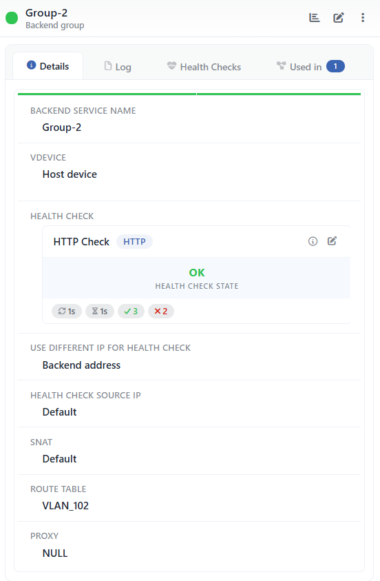 Preview of the Selected Backend Group
| Operation | What it does |
|---|---|
| Dashboard | Opens the Dashboard screen of the group. |
| Edit | Opens the group's edit form in the Edit tab. |
| ⋮ | Opens the menu containing the Log operation, which opens the records of the group in a window. |
There are four tabs in the panel; Health Checks is displayed only if a health check profile is assigned to the group, and Used in only if the group is used in at least one place:
Details
Lists the configuration rows and the health check card of the group (table below).
Log
Lists the user operations (add, edit, delete) performed on the group as a timeline.
Health Checks
Shows the health check result records of the servers in the group combined in a single list.
Used in
Lists the vServices in which the group is used; the badge next to the tab name shows the usage count.
The controls and record format of the Health Checks tab are described on the Health Checks page, and the group-specific combining behavior on the Backend Groups Dashboard page.
The rows in the Details tab are as follows, in order:
| Row | Description | Visibility condition |
|---|---|---|
| Backend Service Name | The name of the group. | Always |
| vDevice | The device on which the group is defined; Host Device on the main device. | Always |
| Health Check | The card of the health check profile assigned to the group: the profile name and type badge, the info and edit icons, the aggregate status of the group (Health Check State), and the profile's Period, Timeout, Required Successes and Required Failures values. If no profile is assigned, the No Check text is displayed. | Always |
| Use Different IP for Health Check | The address at which the health check is performed; Backend Address (each server's own address) if no separate address is defined. | Always |
| Health Check Source IP | The source IP address of the health check packets; Default if not defined. | Always |
| Backup Service | Shows that the group is marked as a backup. | If backup service is checked |
| SSL Service | Shows that TLS is used in the connection to the servers. | If SSL is checked |
| Maintenance Mode | Shows that the group is in maintenance mode. | If maintenance mode is checked |
| Use Frontend Port | Shows that the servers are connected to with the destination port of the request coming to the vService. | If the setting is checked |
| SNAT | The source address translation used in the traffic to the servers; Default if not defined. | Always |
| Route Table | The route table the group is bound to. | Always |
| Proxy | The Proxy Protocol setting of the group; NULL is displayed if the setting has not been saved. | Always |
The per-server Weight, Connection Limit and Cookie Content rows, and the Status Code and DNS Answers rows, which are health check details, are not present in the group preview; the values of the servers are displayed in the list with the Show Backend Services switch.
The "Used in" tab must be checked
The Used in tab enables a quick and accurate analysis of which services a change to be made on the Backend Group will affect. Especially in live environments, since updates to the group settings will immediately affect all bound services, evaluating the possible service impacts before a change is critically important.
Backend Group Add Form
A new Backend Group is added to the TR7 device by following the Load Balancer → Backend Groups → Add steps.
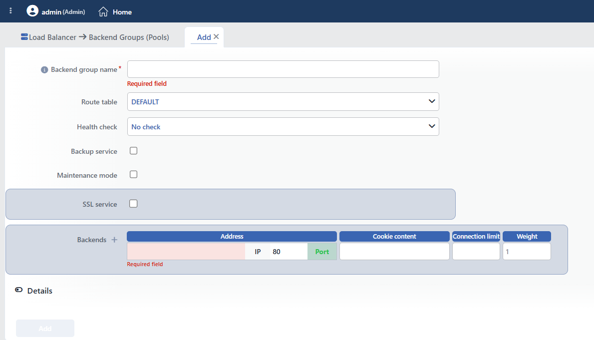 Backend Group Add Form
INFO
Backend Group Name Required
A unique name is entered for the Backend Group to be created. When the field is left empty, the "Required field" warning is displayed, and when a name used in another group is entered, the "Name is used" warning is displayed, and saving is prevented. Uniqueness is checked across groups.
INFO
vDevice
The vDevice on which the group will be defined is selected. This field is displayed only when there is more than one vDevice to choose from; it does not exist in virtual machine setups. While an existing group is being edited, the vDevice cannot be changed.
INFO
Route Table
The route table to be used to access all servers in the group is selected; DEFAULT is selected by default. Route tables make it possible to define separate routing rules for different network segments. If more than one route table is defined, the table that can reach the network where the group is located must be selected; if there is a single table, it should stay as DEFAULT.
The selected route table is applied to all servers in the group; for this reason, all servers in the group must be in the same network segment or reachable over the selected route table.
The route table selection also affects the SNAT IP and Health Check Source IP fields: the device IP lists in these fields are limited to the addresses belonging to the selected route table. Details are on the Route Tables page.
INFO
Health Check
The health check profile to be used to periodically check the reachability and health status of the servers in the group is selected. The options are No Check (default) and the profiles in the profile name (Type) format; a new profile is created with the Add button in the drop-down list, and the created profile is selected automatically.
How it works: The selected profile is applied to each server in the group separately. TR7 sends check requests to each server at the intervals specified in the profile; each server is evaluated independently.
- Check succeeds → the server is marked healthy and continues to receive traffic.
- Check fails → the failure counter increases.
- When consecutive failures reach the Required Failures threshold in the profile → the server is taken out of traffic.
- A server out of traffic continues to be checked; when consecutive successes reach the Required Successes threshold in the profile → it is included in traffic again.
In check types that establish a TLS connection (e.g. HTTPS, TCPS), the SSL settings defined on the group (client certificate, CA profile and SSL security profile) are also applied to the health check connections; if a selection has also been made for these settings in the health check profile, the selection in the profile applies.
Points to consider when selecting a profile:
- Protocol compatibility: the protocol supported by the servers in the group (HTTP, HTTPS, TCP, etc.) should be used.
- Health endpoint: an endpoint that the servers actually respond to should be selected (e.g.
/health,/status,/ping). - Timeout value: it should be higher than the servers' normal response time, but low enough to prevent unnecessary delays.
- Check interval: checking too often burdens the servers, and checking too rarely detects failures late. Usually 5–10 seconds is ideal.
Important
In production environments, Backend Groups with no health check assigned continue to receive traffic even if their servers are unreachable. Defining an appropriate profile for all groups is recommended.
Details are on the Health Checks profile page.
INFO
Enable HC Logs
Enables the health check results to be kept as records; it is on by default. This field is displayed only when a health check profile is selected. The per-server records are monitored from the Health Checks tab of the preview panel; details are on the Health Checks page.
INFO
Backup Service Default: Off
Marks the Backend Group as a backup; it is off by default. When the group is marked as a backup, all servers in the group become active in the vService as backups. When enabled, the group comes into play only when all other main (non-backup) Backend Services and groups bound to the same vService are unavailable; even when it comes into play, only the first available backup server receives traffic at a time.
Use cases: a disaster recovery server group in a different data center, a low-capacity emergency server group, a geographically remote backup site.
INFO
Maintenance Mode Default: Off
Puts the Backend Group into maintenance mode; it is off by default. No traffic is directed to groups in maintenance mode. When enabled, all servers in the group are taken out of traffic regardless of the health check status, and the whole group is put into maintenance at once. While the change is applied, the existing active connections are not cut; they are left to complete, and no new connections are sent to the servers.
Use cases: simultaneous maintenance or update on all servers, temporary disabling during application deployment, troubleshooting and debugging.
INFO
SSL Service Default: Off
Ensures that the connection between TR7 and the servers in the group is made with SSL/TLS encryption; it is off by default. This setting is defined at the group level and applied to all servers. When enabled, TR7 establishes an HTTPS (or TCP over TLS) connection to each server in the group (backend encryption / re-encryption). All servers in the group must be configured to accept SSL/TLS connections; servers can listen for SSL on different ports (443, 8443, etc.), and the port information of each server is defined separately in the Backends section.
Certificate verification: By default (Certificate Verification: None), TR7 does not verify the SSL certificates of the servers:
- Self-signed certificates work without problems.
- Certificates signed by an internal CA are accepted.
- The validity of the certificates presented by the servers is not checked.
- The connection is established even if the certificate has expired.
- Hostname matching (CN/SAN) is not checked.
This default is designed for scenarios where the back-end servers are inside a trusted network (internal network). If certificate verification is needed, Required must be selected in the Certificate Verification field below.
Use cases:
- Providing end-to-end encryption between TR7 and the back-end servers.
- Protecting sensitive data (payment information, personal data).
- Security standards (PCI-DSS, HIPAA) that require encryption.
- Corporate infrastructures where internal CA certificates are used.
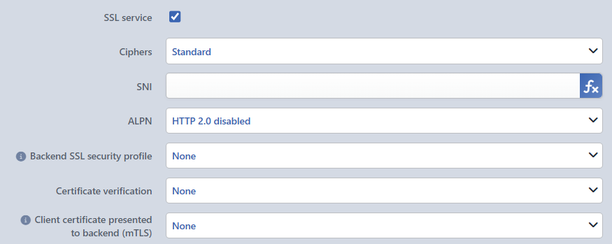 SSL Service
Ciphers
The cipher suite group to be used in the SSL/TLS connections made to all servers in the group is selected. A cipher suite is the combination of the encryption algorithm, the key exchange method and the message authentication algorithm.
- Standard: TR7's default cipher setting is used; it is suitable for current servers. Default.
- Low: a wide compatibility mode that includes all cipher suites (
ALL:NULL:eNULL:aNULL:RC4-MD5:@SECLEVEL=0). It should be used only for mandatory compatibility with legacy servers; it carries a security risk.
If a Backend SSL Security Profile is selected, this field is not taken into account; the cipher list comes from the profile.
SNI
The Server Name Indication (SNI) value is determined. SNI is a TLS extension, sent in the ClientHello message during the TLS handshake, that tells the server for which hostname it should present a certificate (RFC 6066). This SNI value is sent in the connection to all servers in the group. If the servers use the same hostname (virtual hosting / name-based SSL), the SNI value should be defined. The entered value is assigned to a transaction variable by TR7 and used as the sni parameter in the TLS connection. A fixed domain name can be written in the field, or Smart Variables can be added with the fx button next to it; in that case, the SNI is recalculated for each request.
TIP
Common use: Forwarding the Host header of the incoming request to the servers in the group as is. When the fx button next to the field is pressed, the window opens directly with the Request HTTP header content variable and with Host written in the Header name field; it is added to the field with Submit, and the ↓H badge appears in the field. It is used in scenarios where SNI is mandatory and multiple domain names are hosted on the servers in the group; SNI is added this way on Windows IIS when Require Server Name Indication is enabled, and in ADFS services.
This variable reads the HTTP header of the request. Since the header cannot be read in an L7 TCP vService, a fixed domain name must be written in the field.
ALPN
Application-Layer Protocol Negotiation (ALPN) enables the application layer protocol to be determined during the TLS handshake (RFC 7301).
- HTTP 2.0 Disabled: all servers are connected to with HTTP/1.1; no ALPN offer is made. Default.
- HTTP 2.0 Enabled: the connection is made with
alpn h2,http/1.1; HTTP/2 (h2) is tried first, and if it is not supported, a fallback to HTTP/1.1 is made. All servers in the group must support HTTP/2 and serve over TLS.
Backend SSL Security Profile
Defines the cryptographic security parameters (protocol version range and cipher suites) to be used in the SSL/TLS connection TR7 establishes to Backend Services. A profile from TLS Security Profiles is selected. Only the Min. SSL Version, Max. SSL Version, Cipher Algorithms and (in supporting versions) curve parameters of this profile are used; the other settings in the profile have no effect on this connection. When a profile is selected, TR7 limits the Backend Service connections with these security parameters, and the TLS handshake process with the Backend Service is performed according to these rules.
Scenarios:
- Corporate applications with a TLS version restriction on the Backend Service.
- Environments where legacy systems and modern TLS configurations are used together.
- Standardization of cipher and TLS version in line with security policies.
Certificate Verification
It is determined whether the server certificate will be verified in the TLS connection TR7 establishes with the Backend Service (it affects only the TR7 → Backend Service direction and is independent of the client-side SSL).
- None: the certificate is not verified: self-signed certificates and certificates signed by an internal CA are accepted; the validity period, chain and hostname (CN/SAN) are not checked. Default.
- Required: the certificate is verified mandatorily: the trusted CA signature, chain validation, validity period and CN/SAN matching are checked.
Verification CA Profile
It appears when Required is selected in the Certificate Verification field. The CA profile to be used for verification is selected from the profiles on the Certificate Authorities (CA) screen.
Client Certificate Presented to Backend (mTLS)
Enables TR7 to use a client certificate in the TLS connection with the servers in the group. When a certificate is selected, TR7 presents this certificate to the server during the handshake; the server can verify TR7 according to this certificate (mTLS / client certificate authentication). The certificate affects only the TR7 → server connection. The selection is made from among the client certificates and certificates on the SSL/TLS Certificates screen; the default is None.
INFO
Backends Required
It is the table in which the servers to be included in the Backend Group are defined. The servers are entered as a table in which each row corresponds to a server; the four fields in the row are per server and are defined separately for each server. All other settings in the form (health check, SSL, SNAT, route table, maintenance mode, backup, proxy, etc.) are at the group level and are applied to all servers as is.
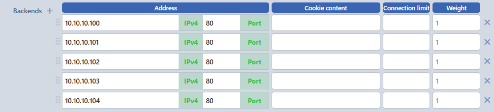 Defining Multiple Backends
| Column | Description |
|---|---|
| Address | The IP:Port information of the server. When the IP is left empty, the "Required field" warning is displayed, and for an invalid port, the "Invalid port" warning; the port comes as 80 by default. |
| Cookie Content | The cookie value that identifies this server in cookie-based session persistence. |
| Connection Limit | The maximum number of concurrent connections allowed to this server (1–65535). |
| Weight | The relative weight of the server in traffic distribution (1–256). |
Row operations: A new server row is added with the + button next to the Backends label. A row is deleted with the × at the end of each row; when a single row remains, × is not displayed and the last row cannot be deleted. When there are two or more rows, the rows are reordered by dragging from the handle on their left. There is no upper limit on the number of servers that can be added.
WARNING
If the same IP:Port pair is entered in more than one row, the form gives no warning; two separate server rows going to the same target are written to the configuration. The uniqueness of the rows should be checked.
These four fields are described in detail below.
INFO
Address (IP:Port) Required
The IP address and port information that determine the location of the server on the network are entered. A different IP:Port combination can be defined for each server in the group.
IP Address
An IP address in IPv4 or IPv6 format, or a domain name (FQDN) that can be resolved with DNS, can be entered.
- IPv4 address:
192.168.1.10,10.0.0.5 - IPv6 address:
2001:db8::1,fe80::1 - FQDN (domain name):
web01.internal.company.com,api.backend.local
Port
The port number the server listens on is entered; for an invalid value, the "Invalid port" warning is displayed.
| Port | Protocol | Use |
|---|---|---|
| 80 | HTTP | Standard web server |
| 443 | HTTPS | SSL/TLS web server |
| 8080 | HTTP | Alternative web port |
| 8443 | HTTPS | Alternative SSL port |
| 3306 | MySQL | Database server |
| 6379 | Redis | Cache server |
The servers in the group can run on different ports. For example, in a group, server-1 can listen on port 80 and server-2 on port 8080; however, in this case, all servers must support the same protocol.
Adding a server: A new server row is added by clicking the + button next to the Backends heading. Unlike the Backend Services screen, no automatic naming is done; the group is always created as a single record, and the servers are the rows within this record. The group members have no separate name; they are referred to in the interface by their IP:Port information.
INFO
Cookie Content
When cookie-based persistence is used, the cookie value that identifies this server is determined. A different cookie content can be defined for each server. When the Cookie Based Connection Persistency action is active in the vService, the cookie value the client receives determines which server it will be directed to.
Readable manual values such as server1, node-01 and backend-a are useful for troubleshooting; meaningful and unique cookie values should be assigned to each server. Characters in the value other than letters, digits and hyphens are reflected in the configuration as _.
INFO
Connection Limit
The maximum number of concurrent connections that can be directed to this server is determined; a different connection limit can be defined for each server. Value range: 1–65535. For a value outside the range, the "Connection limit must be in range 1-65535" warning is displayed. When the limit is reached, new connections are directed to the other servers in the group (those that have not exceeded their limit and are healthy are preferred). When left empty, the number of connections is not limited for that server.
Use cases: assigning different limits to servers with different capacities, gradual loading of a newly added server, preventing specific servers from being overloaded.
INFO
Weight
The relative weight of the server in traffic distribution is determined; it is used in weighted round-robin and similar algorithms. A different weight value can be defined for each server. Value range: 1–256; while the field is empty, 1 is applied. For a value outside the range, the "Weight must be in range 1-256" warning is displayed. Servers with a higher weight receive proportionally more traffic than those with a lower weight; the traffic distribution is calculated according to the sum of the weights of all servers in the group.
Mathematical calculation:
Server Traffic Percentage = (Server Weight / Total Weight) × 100Example 1: When the weights in a three-server group are 1, 2 and 3 (total weight 6):
- Server-1: (1/6) × 100 = 16.7% traffic
- Server-2: (2/6) × 100 = 33.3% traffic
- Server-3: (3/6) × 100 = 50.0% traffic
Example 2: Servers with different capacities (total weight 14):
- Server-A: 32 vCPU, 64 GB RAM → Weight: 8
- Server-B: 16 vCPU, 32 GB RAM → Weight: 4
- Server-C: 8 vCPU, 16 GB RAM → Weight: 2
- Traffic distribution: 57%, 29%, 14%
Use cases:
- Capacity-based distribution: load proportional to different hardware capacities; powerful servers receive a higher weight.
- Canary deployment: a low weight (e.g. 1) for the new version on a single server, a high weight (e.g. 10) for the others; if it works without problems, the weight is increased gradually.
- Blue-Green deployment: Blue (old) a high weight (e.g. 10), Green (new) the lowest weight (
1); traffic is shifted gradually to Green (2, 5, 10…). - Geographic optimization: latency improvement with a higher weight for the data center close to the user.
- Cost optimization: cost/performance balance with a low weight for expensive servers and a high weight for economical servers.
INFO
Details
Advanced configuration fields are accessed by turning on the Details switch at the bottom of the form; the switch is off by default when adding and editing. The following fields are in this section; they are defined at the group level and applied to all servers in the group. The per-server Cookie Content, Connection Limit and Weight are not in this section but in the Backends table.
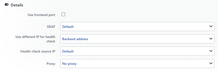 Backend Group Details Section
INFO
Use Frontend Port Default: Off
Dynamically determines the destination port to be used in the connection to the servers in the group; it is off by default and applied to all servers. When enabled, the original destination port of the request coming to the vService is used instead of the port defined for the servers.
Warning
While this option is enabled, the port values entered in the Backends table are ignored for traffic; the health check still uses the port in the row. All servers in the group must be listening on the vService ports.
INFO
SNAT
The Source Network Address Translation settings are configured. It determines the source IP that TR7 will use when connecting to the servers in the group; this setting is applied to all servers.
Default
The source IP is determined by the routing rules of the selected route table. All servers in the group see the same IP address of TR7 as the source.
TIP
In HTTP vServices, the real client IP address can be forwarded to all servers in the group with the X-Forwarded-For request header.
Use Client IP
The real (original) IP address of the client is used as the source IP in the connections made to the servers in the group (transparent / source IP preservation).
Requirements:
- The response traffic of all servers in the group must return through TR7.
- For this, the default gateway of the servers must be TR7, or the Spoofing feature below must be used.
Use cases:
- Logging with the real client IP on all servers in the group.
- IP-based access control.
- Rate limiting applications.
Use Device IP
One of the device IPs is selected and used as the source for the connection to all servers in the group. The list in the SNAT IP field displayed when this option is checked is limited to the addresses belonging to the Route Table selected in the form, and the first address is selected automatically.
Use cases:
- Identifying the traffic coming from a specific source IP on all servers in the group.
- Source IP filtering in firewall rules.
- Traffic separation in multi-tenant environments.
INFO
Spoofing Default: Off
This field is displayed only while Use Client IP is selected in the SNAT field; it is off by default. When enabled, TR7 performs ARP spoofing on the network where the servers in the group are located and ensures that the servers' response traffic returns through TR7; in this way, the client IP can be preserved without the need to change the default gateway of the servers. The setting is at the group level and applies to all servers.
Spoofing IP VIP Condition
The condition that binds on which device spoofing will run to a cluster VIP is selected. When a VIP is selected, spoofing runs on the device where the VIP is active; when None is selected, it runs only on the device selected in the Spoofing Default Device field. This field is not displayed while clustering is off.
Spoofing Default Device
In cluster setups, the device that will perform spoofing by default is selected; the options are the names of the devices in the cluster, and the first device is selected by default. This field is not displayed while clustering is off.
Spoofing IP
The IP address that spoofing will target is entered. When left empty, the default gateway of the selected route table is targeted.
INFO
Use Different IP for Health Check
It is determined whether the health check will be performed on the servers' own addresses in the group or on a different address.
Backend Address
By default, the health check is performed separately on each server's own IP:Port address in the group.
Different Address
The health check is performed on a single address entered in the IP and port fields that open. The check is sent to this address separately for each server; in practice, the result is the same on all servers, and the status of this address affects all servers in the group. A domain name is not accepted in this field, and the port is required.
Use cases:
- If a load balancer VIP address in front of the servers is to be checked.
- If a central health endpoint reports the status of all servers.
INFO
Health Check Source IP
The source IP from which the health check requests will be sent is selected. This source IP is used in the health checks made to all servers in the group.
Default
The source IP is determined by the routing rules of the selected route table.
Device IP
One of the device IPs is selected from the list that opens; the list is limited to the addresses belonging to the Route Table selected in the form. It is used when health check traffic needs to be allowed on the servers from specific IPs.
INFO
Proxy
Proxy Protocol is a protocol that preserves the real client IP and port information in the connections TR7 forwards to the servers in the group. The client IP/port information is forwarded to the back-end server at the very beginning of the connection, before the application data starts. This setting is defined at the group level and applied to all servers. In this way, correct logging with the real client IP, IP-based access control and correct rate limiting are achieved on the back-end side, and client information is preserved in non-HTTP TCP services as well.
Important requirement
All servers in the group must support Proxy Protocol and be configured to expect it. If a Proxy header is sent to a server that does not support it, the server interprets this data as application data and the connection fails.
No Proxy
Proxy Protocol is not used; the servers in the group see TR7's IP as the source IP. Default value.
When it is used:
- If the back-end servers do not support Proxy Protocol.
- If an HTTP vService is used and the X-Forwarded-For header is sufficient.
- If the back-end servers do not need the client IP.
Proxy
Text (ASCII)-based Proxy Protocol (v1). Client information is sent to all servers in the group in a human-readable format.
Format example:
text
PROXY TCP4 192.168.1.100 10.0.0.50 54321 80\r\nPROXY: protocol identifierTCP4: transport protocol (TCP4 or TCP6)192.168.1.100: client IP address (source)10.0.0.50: TR7 IP address (destination)54321: client port number80: destination port number\r\n: end of line (CRLF)
Advantages:
- Simple and widely supported.
- It has a human-readable structure (ease of troubleshooting).
- It is compatible with HTTP and general TCP services.
Disadvantages:
- It uses more bytes than binary.
- The parsing overhead is higher.
Supporting software: NGINX, Apache (mod_remoteip), HAProxy, Envoy, Caddy.
Proxy v2
A more advanced Proxy Protocol version that works in binary format. It has the same basic purpose as the Proxy (v1) option but offers a higher-performance and extensible structure.
Advantages:
- It works more efficiently thanks to the binary format (fewer bytes, faster parsing).
- IPv4 and IPv6 support is standard.
- It allows additional meta information to be carried (TLV: Type-Length-Value fields).
- It is more suitable for high-traffic and complex architectures.
- SSL/TLS information (cipher, protocol version) can be added.
Disadvantages:
- It is not human-readable (binary format).
- It is supported by less software (compared to v1).
When is it preferred?
- If high performance is needed.
- If additional meta information needs to be carried.
- If the modern back-end infrastructure supports v2.
Configuration check. Before Proxy Protocol is enabled, it should be verified that the servers are configured correctly:
- NGINX: the
listen 80 proxy_protocol;andset_real_ip_fromdirectives. - Apache: the
mod_remoteipmodule withRemoteIPProxyProtocol On.
Usage Location
Backend Groups, just like individual Backend Services, are building blocks that do not work independently. After a group is defined, an association with a vService must be made in order to send traffic to it. The group is added to the Default Backend Services or Conditional Backend Services list of the vService.
In the backend selector in the vService form, groups and individual services are offered in the same list; with the Type filter in the list, only groups or only individual services can be displayed. In the selector, the address column of a group shows not the member addresses one by one but the number of servers in the Total of N format. With the Backend Group button above the selector, a new group can be created without leaving the vService form and added directly to the list.
When the configuration is applied, the group is opened as a separate target for each server in the group: the address, weight, cookie content and connection limit come from the related server's row; all other settings come from the group definition. For this reason, the load balancing algorithm evaluates the group not as a single target but all of its servers as separate targets.
The traffic flow, condition-based distribution (Content Switching), practical usage steps and real-life scenarios are described in the Usage Location section of the Backend Services page; the only difference is that a group is added to the related lists instead of an individual service.