
Smarter by Design.Simpler for Business
Add Interface (Cluster)
What Is Add Interface?
Add Interface is a fundamental configuration operation that makes it possible to build flexible and scalable network architectures by creating logical network structures beyond the physical network interfaces. Besides the physical interfaces (the ETH ports), TR7 supports the VLAN, VXLAN, V-ETH, V-ETH(Peer), Bond, LACP and Bridge interface types.
Although these interfaces are technically virtual/logical, they make it possible to apply advanced network features such as segmentation, redundancy, bandwidth increase and isolation on the physical hardware. Every interface added is created on a specific route table and is subject to the routing rules of that table.
Cluster / Standalone
This page describes the interface adding form used while clustering (cluster) is enabled. The adding form is exactly the same as the one in a standalone setup; the VIP fields specific to the cluster (VIP communication, VIP communication (v6), VIP transition duration (s), VIP transition method) are not present in the adding form; after the interface is created, the VIP communication fields are seen in the Edit Interface form; the VIP transition fields, on the other hand, appear only after a VIP communication pair is selected. For the standalone version see the Interfaces (Standalone) page.
Adding an interface in a cluster
- The interface definition is kept in the common configuration; if the cluster connection is open, the synchronization versions are compatible and automatic synchronization is enabled, the record is applied on both devices, otherwise it is applied on this device only; the synchronization state appears as Cluster Disconnected while the cluster is broken and as Cluster out of sync when the peer device connects, and it is not synchronized automatically when the connection is established again; in order to transfer it to the peer device, Sync All must be run from the Sync Status screen.
- The new interface is listed on the Interfaces List screen with the two-colored indicator that shows the status of the two devices together.
- In order to assign a VIP to the interface, Ip type = VIP is selected in the Add IP Address form; in order for the VIP to work, there must be an Interface IP pair on the interface whose address is defined for both devices and it must be selected as the VIP communication in the Edit Interface form; the required virtual router ID is assigned automatically by TR7 when the pair is selected.
The interface types that can be added on TR7:
| Interface Type | Standard | Purpose of Use |
|---|---|---|
| VLAN | IEEE 802.1Q | Network segmentation and broadcast domain isolation |
| VXLAN | RFC 7348 | An overlay network that tunnels a Layer-2 network over Layer-3 |
| V-ETH | MACVTAP | A virtual interface with an independent MAC address on a master interface |
| V-ETH(Peer) | Virtual Ethernet | Communication between route tables |
| Bond | Balance-rr | Round-robin load balancing |
| LACP | IEEE 802.3ad | Redundant and high-bandwidth connectivity |
| Bridge | Linux bridge | L2 switch functionality |
7 Interface Types
Logical network structures
VLAN · VXLAN · V-ETH · V-ETH(Peer) · Bond · LACP · Bridge
Route Table
Isolated environment
Every interface is created in a route table
Bond / LACP
Redundancy
Link aggregation and failover
VLAN / VXLAN
Segmentation
802.1Q separation and L2 overlay over L3
Why Is Add Interface Important?
In modern data center and enterprise network environments, physical interfaces alone may be insufficient to meet complex network requirements. By creating additional interfaces, logical network layers can be built on the physical infrastructure; this provides flexibility, security and performance optimization.
- Network Segmentation and Isolation: Thanks to VLANs, dozens of logical networks isolated from one another can be created on a single physical interface; security policies are applied, broadcast traffic is limited and department-based network separation is done.
- Overlay Networks: VXLAN interfaces make it possible for the networks in different locations to meet in the same broadcast domain by tunneling Layer-2 segments over a Layer-3 network.
- High Availability: Bond and LACP interfaces combine multiple physical connections to provide both redundancy and an increase in total bandwidth; if one connection fails, the traffic is directed to the others automatically.
- Route Table Integration: V-ETH(Peer) interfaces make it possible for the networks that work isolated in different route tables to communicate in a controlled way; this is critical in multi-tenant environments.
- L2 Connectivity: Bridge interfaces connect different interfaces to the same broadcast domain and offer L2 switch functionality; this is required for the scenarios that work in transparent (bridge) mode.
Interface Types and Use Cases
VLAN IEEE 802.1Q
Creates logical network segments on a single physical interface; every VLAN defines a different broadcast domain with a unique VLAN ID. Department-based separation, guest network isolation, VoIP (voice/data) separation, DMZ segmentation.
VXLAN RFC 7348
It carries the Layer-2 segment defined by a VNI across a Layer-3 network by tunneling it over UDP; it can work with a single remote peer, with multiple peers or with a multicast group. L2 extension between locations, overlay data center networks.
V-ETH MACVTAP
Creates a virtual interface with a MAC address independent of the main interface, on a master interface. Container/VM network connections, direct access to virtual devices, test/development environments.
V-ETH(Peer) Virtual Ethernet
Creates a virtual ethernet cable between two ends; the ends can be in different route tables and routing is done between them. Controlled communication between isolated route tables, access to a common service in multi-tenant environments.
Bond Balance-rr
Combines multiple physical interfaces with the Round-Robin algorithm; the packets are sent from different interfaces in turn. It does not require switch support. It is suitable for simple load balancing and test environments.
LACP IEEE 802.3ad
The industry standard link aggregation protocol; by working in coordination with the switch, it provides both redundancy and an increase in bandwidth. Production environments that require high availability, data center uplinks and critical infrastructure connections.
Bridge Linux bridge
Creates a virtual L2 switch by connecting multiple interfaces to the same L2 segment; all the connected interfaces are in the same broadcast domain. Transparent (bridge) mode setups and L2 pass-through scenarios.
Best Practices
- Use a consistent standard in interface naming. Determine a convention that reflects the purpose of use and the type (e.g.
vlan100_dmz,bond0_uplink,lacp0_dc). This makes interface management easier in large environments. - Prefer LACP over Bond in production environments. In critical connections use LACP instead of a Balance-rr Bond; by working in coordination with the switch, it offers more reliable redundancy and consistent performance. Bond should be preferred only in environments where there is no switch support or in test environments.
- Plan the VLAN IDs. Plan the VLAN ID ranges according to the department, the security level or the traffic type (e.g. 10–99: Management, 100–199: User, 200–299: Server).
- Select the route table carefully. An interface added to the wrong route table may cause unexpected traffic flows. Especially in V-ETH(Peer) connections, make sure that both ends are assigned to the correct tables.
- Select the members and the master interfaces according to the rules. The selection lists are not filtered in the form; when an unsuitable master interface or member is selected, the record is rejected by the server. Make sure that the Bond/LACP members are physical ports that have no IP, route or sub-interface on them.
- Enable TCP acceleration when needed. Enable it only on high-traffic interfaces; it is not necessary in every scenario.
- STP awareness on Bridge interfaces. When creating a Bridge, evaluate the Spanning Tree Protocol (STP) configuration on the switch side of the connected interfaces; a wrong configuration may cause L2 loops.
How to Add?
The following steps are followed in order to add a new interface on the TR7 device:
- The Configuration Menu is opened by clicking the TR7 logo at the bottom left.
- The Network → Interfaces → Actions → Add interface steps are followed; the form opens as a closable tab inside the list screen.
- In the form that opens, the interface type to be added is selected from the Type field. The physical (ETH) type is seen in the list but cannot be selected; the physical interfaces come with the hardware and can neither be added nor deleted.
- If more than one route table is defined, the Route table in which the interface will be added is determined.
- The configuration fields specific to the interface type are filled in.
- The interface is created by clicking the
Add interfacebutton.
The adding operation does not ask for confirmation; the record returns immediately, the system application starts in the background and the new interface is turned on (up) automatically. If it is a V-ETH(Peer) whose peer has not been selected, it is not created in the system until it is paired (see below). The interface created is displayed on the Interfaces List screen and an IP address can be assigned to it.
Common fields
The Type, Route table (seen only while there is more than one table) and Interface name fields and MTU and TCP acceleration in the Details section below are common to every interface type; below, they are given again in screen order in the form of every type. The VLAN ID and VNI fields take place above the Interface name field in their own types; in the VXLAN type the Details section contains additional fields.
WARNING
While a network operation continues (while the "Network is under action. Please wait..." warning is seen), the Add interface menu does not become passive; a record sent during this time is rejected by the server and is shown as an error. The completion of the operation must be waited for.
The VLAN (IEEE 802.1Q) Add Interface Form
A VLAN interface is added in order to create logical network segments on a single physical interface.
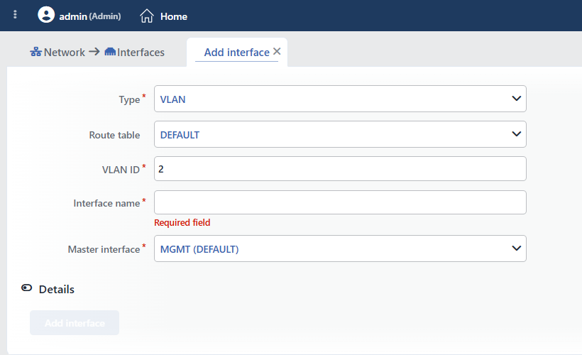 The VLAN (IEEE 802.1Q) Add Interface Form
INFO
Type
VLAN is selected; when the form is opened, this type comes selected by default. VLAN (IEEE 802.1Q) is the industry standard protocol used in order to create logical network segments on a single physical interface.
INFO
Route Table
The route table in which the VLAN interface will be created is selected; every route table has its own routing rules. This field is seen only if more than one route table is defined; if there is a single table, the interface is created automatically in the DEFAULT route table. While there is more than one table, if a specific table is selected in the Route table filter on the list screen, that table comes as the default, and if the filter is in the All route tables position, DEFAULT does. For the details see the Route Tables page.
INFO
VLAN ID
The VLAN identifier is entered (2 – 4094, default 2). It is used in order to distinguish different VLANs on the same master interface; the same VLAN ID cannot be defined a second time on the same master interface. For a value outside the range the "VLAN ID must be in range 2-4094" warning is given.
INFO
Interface Name
A unique and descriptive name is entered for the VLAN interface (1–15 characters; it starts with a letter or a digit and can then contain the a–z, 0–9, _, ., - characters; capital letters can also be used, the name matching is case-sensitive). When a name that is in use is entered, the "Name is used" warning, and for a name that does not follow the rule, the "Invalid input for "Interface name"" warning is given. A format that reflects the purpose of use is recommended (e.g. vlan100_dmz, vlan200_users).
INFO
Master Interface
The master interface on which the VLAN will be created is selected. All the interfaces on the device are offered in the list; the interfaces that are bond/LACP members are passive. Only the interfaces of the physical (ETH), Bond or LACP type are accepted as the master interface; if another type is selected, the record is rejected by the server. In order for the tagged VLAN traffic to be able to pass, the switch port the selected master interface is connected to must be configured (trunk/tagged) to carry the related VLANs.
INFO
Details
By clicking the Details header row, the advanced settings (MTU, TCP acceleration) are opened; the section is closed by default.
 Details
MTU
The maximum transmission unit (Maximum Transmission Unit) value of the interface is entered. When the field is left empty, the MTU is not set and the default value the kernel derives from the master interface applies (in VXLAN 50 bytes smaller than the MTU of the master interface); entering 0 gives the same result as well. An existing MTU cannot be reset with this field. No upper limit is enforced in the form; in the environments that require jumbo frames, values such as 9000 can be used, but the value must be consistent with the MTU on the master interface and on the switch side. The MTU is applied in the system synchronization pass after the adding.
TCP Acceleration
When it is enabled, Receive Flow Steering (RFS) is turned on on the interface: the incoming packets are directed to the CPU core on which the application that handles the related connection runs; in this way the cache locality increases and the performance improves on high-traffic interfaces. It is closed by default.
INFO
Add Interface
The VLAN interface is created by clicking the Add interface button. While there is an erroneous field in the form, the button is passive. The record is applied in the background without confirmation being asked, the interface is turned on automatically and the form tab closes; if the server rejects the record, an error window opens and the form stays open.
The VXLAN Add Interface Form
A VXLAN interface is added in order to tunnel a Layer-2 segment over a Layer-3 network.
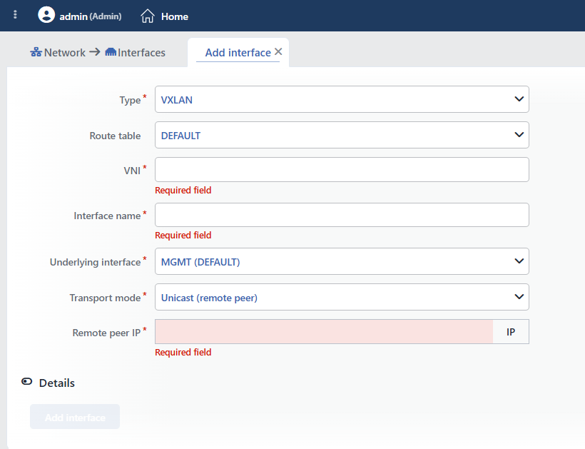 The VXLAN Add Interface Form
INFO
Type
VXLAN is selected. VXLAN carries the Layer-2 segment defined by a VNI (VXLAN Network Identifier) over a Layer-3 network inside UDP packets.
INFO
Route Table
The route table in which the VXLAN interface will be created is selected; if no custom table has been added, the interface is added automatically to the DEFAULT route table.
INFO
VNI
The VXLAN network identifier is entered (1 – 16777215; it is required and has no default value). The same VNI cannot be defined a second time in the same route table. For a value outside the range the "VNI must be in range 1-16777215" warning is given.
INFO
Interface Name
A unique and descriptive name is entered for the VXLAN interface (the rules are the same as the Interface name field in the VLAN form).
INFO
Underlying Interface
The underlying interface over which the tunnel packets will be sent and received is selected. All the interfaces on the device are offered in the list; the bond/LACP members are passive. Only the interfaces of the ETH, VLAN, Bond or LACP type are accepted as the underlying interface; if another type is selected, the record is rejected by the server.
INFO
Transport Mode
How the tunnel will reach the far ends is selected; according to the selection only one of the fields below is seen:
- Unicast (remote peer): it works with a single remote peer. Default.
- Unicast (multiple peers): more than one remote peer is defined.
- Multicast group: the ends are found over a multicast group.
Remote Peer IP
It is seen when Unicast (remote peer) is selected. The IP address of the far end is entered; it is required.
Peer IPs
It is seen when Unicast (multiple peers) is selected. The IP addresses of the far ends are added row by row; at least one address is required. When the same address is entered twice, the "Elements must be unique" warning is given; all the addresses must be in the same IP version (IPv4 or IPv6).
Multicast Group
It is seen when Multicast group is selected. The multicast group address to be used is entered; the address must really be in the multicast range, otherwise the record is rejected by the server.
INFO
Details
By clicking the Details header row, the advanced settings are opened; the section is closed by default. In the VXLAN type there are additional fields in this section:
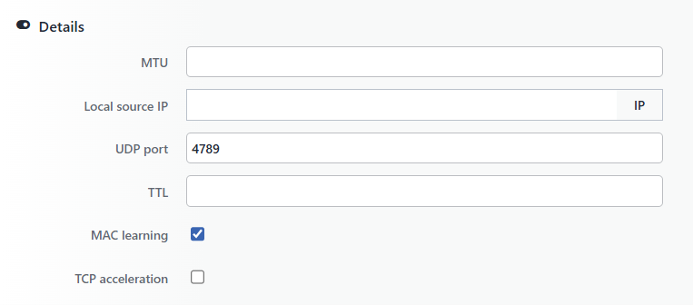 The VXLAN Details Section
MTU
It is the same as the MTU field in the VLAN form. Because of the tunnel header, the MTU of the VXLAN interface must be kept smaller than the MTU of the underlying interface.
Local Source IP
The local IP address to be used as the source in the tunnel packets is entered; it is optional. When it is entered, it must be in the same IP version as the far end addresses.
UDP Port
The UDP destination port to be used for the tunnel is entered (1 – 65535, default 4789).
TTL
The TTL value of the tunnel packets is entered (1 – 255); it is optional.
MAC Learning
It makes it possible for the MAC addresses learned from the remote peers to be recorded dynamically; it is on by default.
TCP Acceleration
It is the same as the TCP acceleration field in the VLAN form.
INFO
Add Interface
The VXLAN interface is created by clicking the Add interface button; the behavior is as in the VLAN form.
The V-ETH (MACVTAP) Add Interface Form
A V-ETH interface is added in order to create a virtual interface with a MAC address independent of the main interface, on a master interface.
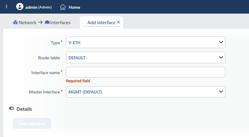 The V-ETH (MACVTAP) Add Interface Form
INFO
Type
V-ETH is selected. V-ETH (MACVTAP) creates a virtual interface that works in bridge mode on the selected master interface. This interface works with a MAC address independent of the MAC address of the master interface.
INFO
Route Table
The route table in which the V-ETH interface will be created is selected; if no custom table has been added, the interface is added automatically to the DEFAULT route table.
INFO
Interface Name
A unique and descriptive name is entered for the V-ETH interface (the rules are the same as the Interface name field in the VLAN form).
INFO
Master Interface
The master interface on which the V-ETH will be created is selected. All the interfaces on the device are offered in the list; the bond/LACP members are passive. Only the interfaces of the ETH, VLAN, Bond or LACP type are accepted as the master interface; if another type is selected, the record is rejected by the server.
INFO
Details
By clicking the Details header row, the advanced settings (MTU, TCP acceleration) are opened; the section is closed by default. The fields are the same as in the VLAN form.
Details
INFO
Add Interface
The V-ETH interface is created by clicking the Add interface button; the behavior is as in the VLAN form.
The V-ETH(Peer) Add Interface Form
A V-ETH(Peer) interface is added in order to create a virtual ethernet cable between two ends. The pair is set up with two separate adding operations: first the first end is created without a peer, then, while the second end is being added, the first end is selected as the peer.
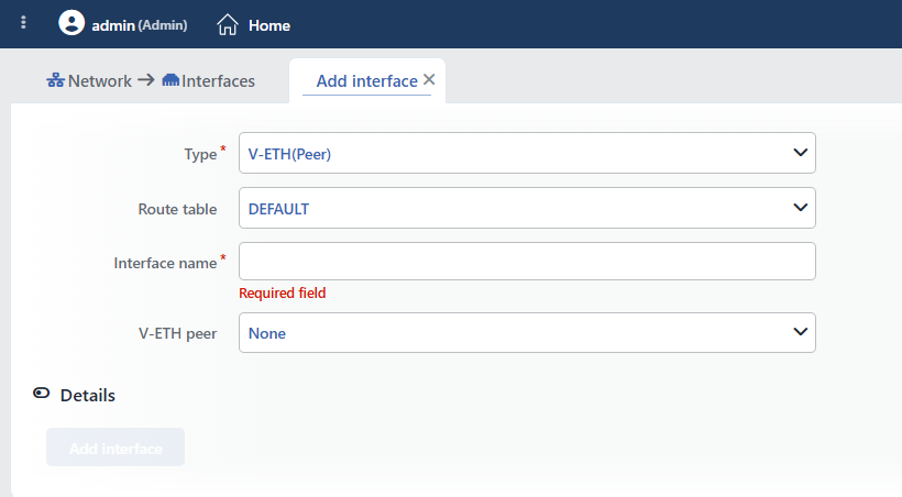 The V-ETH(Peer) Add Interface Form
INFO
Type
V-ETH(Peer) is selected. It creates a virtual ethernet cable between two ends; by placing the ends in different route tables, the tables that are isolated from one another are made to communicate in a controlled way.
INFO
Route Table
The route table in which this end of the V-ETH(Peer) interface will be created is selected. Every end carries its own route table; for communication between the tables, the other end is expected to be created in a different route table, but the form does not enforce this.
INFO
Interface Name
A unique and descriptive name is entered for the V-ETH(Peer) interface (the rules are the same as the Interface name field in the VLAN form). Consistent naming is recommended in peer pairs (e.g. veth_rt1_rt2, veth_rt2_rt1).
INFO
V-ETH Peer
The peer V-ETH(Peer) interface this end will be connected to is selected. The list consists of the None option and the V-ETH(Peer) interfaces that have not been paired yet; the field is not required and is left as None while the first end is being added. When the first end is selected while the second end is being added, the two interfaces are paired with each other.
WARNING
An end whose peer is None is seen in the configuration and in the list, but it is not created as a network device in the system until the second end is paired with it. In order for the pair to work, both ends must be added and IP addresses must be assigned to the interfaces.
INFO
Details
By clicking the Details header row, the advanced settings (MTU, TCP acceleration) are opened; the section is closed by default. The fields are the same as in the VLAN form.
Details
INFO
Add Interface
The V-ETH(Peer) interface is created by clicking the Add interface button; the behavior is as in the VLAN form.
The Bond (Balance-rr) Add Interface Form
A Bond interface is added in order to combine multiple physical interfaces with Round-Robin.
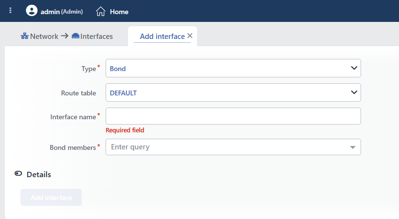 The Bond (Balance-rr) Add Interface Form
INFO
Type
Bond is selected. Bond (Balance-rr) combines multiple physical interfaces as a single logical interface; the packets are sent from different physical interfaces in turn with the Round-Robin algorithm. TR7 creates this interface at the kernel level with the mode=balance-rr and miimon=100 (100 ms link monitoring interval) parameters; these parameters cannot be changed from the form.
WARNING
The Bond (Balance-rr) mode does not require a special configuration on the switch side but in some scenarios it may cause packet ordering problems. The use of LACP is recommended in production environments.
INFO
Route Table
The route table in which the Bond interface will be created is selected; if no custom table has been added, the interface is added automatically to the DEFAULT route table. The member interfaces are moved automatically to the route table of the bond during the record.
INFO
Interface Name
A unique and descriptive name is entered for the Bond interface (the rules are the same as the Interface name field in the VLAN form; e.g. bond0_uplink, bond1_storage).
INFO
Bond Members
The physical interfaces to be included in the Bond are selected; multiple selection can be made. All the interfaces on the device are offered in the list and the list is not filtered; during the record the server applies the following rules:
- The members must be physical (ETH) interfaces.
- There must be no IP address, route, VLAN, VXLAN or V-ETH on the members (e.g. the "Interface '...' has N IPs" error).
- The members must not be another bond/LACP or bridge member or a protected interface (one that carries a management access IP or is the cluster synchronization interface).
It is recommended that all the selected interfaces be in the same speed and duplex mode.
WARNING
The form allows saving without a member being selected; a bond without members is non-functional. At least two physical interfaces must be selected.
INFO
Details
By clicking the Details header row, the advanced settings (MTU, TCP acceleration) are opened; the section is closed by default. The fields are the same as in the VLAN form.
Details
INFO
Add Interface
The Bond interface is created by clicking the Add interface button; the behavior is as in the VLAN form.
The LACP (IEEE 802.3ad) Add Interface Form
An LACP interface is added for a redundant and high-bandwidth connection coordinated with the switch.
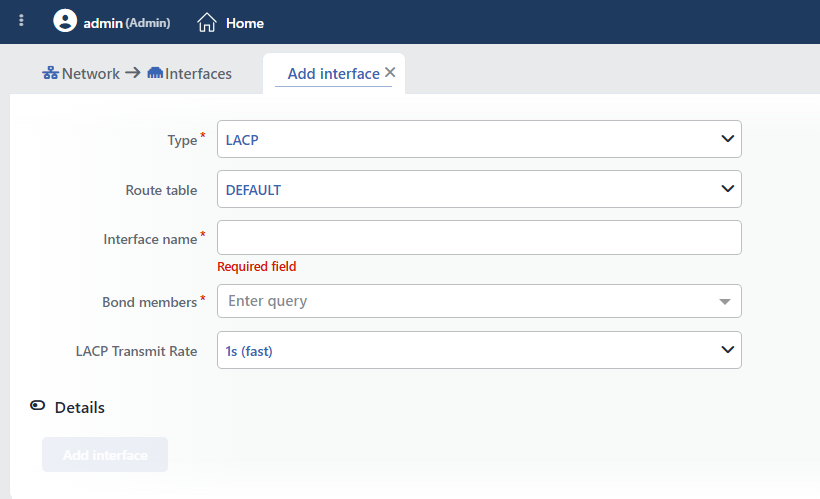 The LACP (IEEE 802.3ad) Add Interface Form
INFO
Type
LACP is selected. LACP (Link Aggregation Control Protocol, IEEE 802.3ad) is the industry standard protocol that provides both redundancy and an increase in total bandwidth by combining multiple physical interfaces in coordination with the switch. TR7 creates this interface at the kernel level with the mode=802.3ad and miimon=100 (100 ms link monitoring interval) parameters; the other 802.3ad parameters such as the hash policy and ad_select stay at the kernel defaults. Only the LACP transmission rate (lacp_rate) can be changed from the form.
INFO
Route Table
The route table in which the LACP interface will be created is selected; if no custom table has been added, the interface is added automatically to the DEFAULT route table. The member interfaces are moved automatically to the route table of the LACP interface during the record.
INFO
Interface Name
A unique and descriptive name is entered for the LACP interface (the rules are the same as the Interface name field in the VLAN form; e.g. lacp0_dc_uplink, lacp1_storage).
INFO
Bond Members
The physical interfaces to be included in the LACP group are selected; multiple selection can be made. The rules in the Bond form apply exactly: the list is not filtered, the members must be physical (ETH) interfaces that have no IP/route/sub-interface on them and that are not attached to another bond/bridge. The selected interfaces must be configured in the same LACP group on the switch side as well.
TIP
At least two physical interfaces must be selected for LACP; the form does not prevent a record without members. Make sure that all the interfaces are in the same speed and duplex settings.
INFO
LACP Transmit Rate
The LACP PDU (Protocol Data Unit) sending rate is selected; this setting determines the LACP synchronization frequency between TR7 and the switch:
- 1s (fast): The LACP PDUs are sent every 1 second. It provides faster failover in a link failure and creates more control traffic. It is recommended for critical connections. Default.
- 30s (slow): The LACP PDUs are sent every 30 seconds. It creates less control traffic and the failure detection is slower. It is suitable for stable environments.
WARNING
LACP Transmit Rate must be compatible with the configuration on the switch side. In case of an incompatibility the LACP group may not work properly.
INFO
Details
By clicking the Details header row, the advanced settings (MTU, TCP acceleration) are opened; the section is closed by default. The fields are the same as in the VLAN form.
Details
INFO
Add Interface
The LACP interface is created by clicking the Add interface button; the behavior is as in the VLAN form.
The Bridge Add Interface Form
A Bridge interface is added in order to create a virtual L2 switch by connecting multiple interfaces to the same L2 segment.
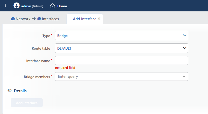 The Bridge Add Interface Form
INFO
Type
Bridge is selected. Bridge creates a virtual L2 switch by connecting two or more interfaces to the same Layer 2 segment. All the interfaces connected to the Bridge are in the same broadcast domain.
INFO
Route Table
The route table in which the Bridge interface will be created is selected; if no custom table has been added, the interface is added automatically to the DEFAULT route table.
INFO
Interface Name
A unique and descriptive name is entered for the Bridge interface (the rules are the same as the Interface name field in the VLAN form; e.g. br0_dmz, br1_internal).
INFO
Bridge Members
The interfaces to be included in the Bridge are selected; multiple selection can be made. All the interfaces on the device are offered in the list and the list is not filtered; during the record the server applies the following rules:
- The members must be in the same route table as the bridge (otherwise the "Must be in the same namespace" error).
- The members must not be a bond/LACP member, a member of another bridge (the "... is a bridge member" error) or a protected interface (one that carries a management access IP or is the cluster synchronization interface).
All the selected interfaces are connected to the same L2 segment and L2 switching is done between them. The form does not prevent a record without members.
WARNING
TR7 creates the bridge with STP off; loop protection must be provided on the switch side. While a bridge is being created, attention must be paid to L2 loops and it must be made sure that the Spanning Tree Protocol (STP) configuration on the switch side is suitable.
INFO
Details
By clicking the Details header row, the advanced settings (MTU, TCP acceleration) are opened; the section is closed by default. The fields are the same as in the VLAN form.
Details
INFO
Add Interface
The Bridge interface is created by clicking the Add interface button; the behavior is as in the VLAN form.