
Smarter by Design.Simpler for Business
Route Tables
What Is Route Tables?
Route Tables makes it possible to separate the network elements (the interfaces, the IP addresses, the routes and the firewall rules) from one another by creating isolated network zones on TR7. It is especially critical in the cases that require more than one default gateway: every route table can define a default gateway of its own (IPv4 and IPv6).
Every route table defines an end-to-end isolated network zone that has its own interfaces, IP addresses, routing table, firewall rules, its own DNS servers and its own L4 DDoS mitigation settings. This structure provides an isolation similar to the VRF (Virtual Routing and Forwarding) concept; at the system level every route table is created as a separate zone that works with its own network stack.
By moving the interfaces to the desired route table, the IP addresses and the route definitions on them are passed onto the selected table as well; because these elements are bound to the interface and pass to the new table together with the interface when it is moved.
TR7 comes with the DEFAULT route table by default (internal id 1, table number 1); this table is always present and cannot be deleted. As additional tables are created, the system assigns a unique internal identity and the smallest free table number starting from 2 to each of them.
Isolated Zone
VRF-like
It has its own interface, IP, route, firewall and DNS settings
Per Table
Default gateway
Every table defines its own default gateway (IPv4/IPv6)
Dinamik Routing
FRR · BGP/OSPF…
Every dynamic table runs its own independent FRR instance
Interface Moving
Segmentation
The interfaces are moved between the tables together with their IPs and routes
DNS · L4 DDoS
Table-based services
DNS servers and an L4 DDoS mitigation configuration specific to every table
V-ETH(Peer)
A bridge between the tables
A veth pair for controlled communication between isolated tables
Why Is Route Tables Important?
In modern network architectures traffic isolation, security segmentation and multi-tenant support are critical requirements. Route tables are the fundamental way of meeting these requirements on TR7.
- Multiple Default Gateways: By defining separate route tables for different uplink lines on a single device, its own default gateway (IPv4 and IPv6) can be assigned to every table; the gateway health is monitored from the Gateway Health column.
- Isolation at the Operating System Level: The isolation is provided not at the application layer but at the base of the network configuration. The interface, IP, route and firewall rules in one table do not leak into the other tables in any way.
- Multi-Tenant Environments: By creating a separate route table for every customer, the risk of an IP collision disappears; different customers can use the same IP ranges, because the IP collision check is done inside the table.
- Security Segmentation: By managing the security zones such as the DMZ, the internal network and the management traffic in separate tables, the security policies are applied more effectively. Since the Firewall rules are also bound to the route table, every zone runs its own policy isolated.
- Table-Based Network Services: The DNS servers (Device DNS) and the L4 DDoS mitigation settings can be configured separately for every route table; in this way different segments can work with different name resolution and protection profiles.
- Independent Dynamic Routing: Every dynamic table runs its own FRR instance; the BGP/OSPF neighborships and the route decisions in one table are managed without affecting the other tables.
- Controlled Communication Between the Tables: When full isolation is required, the tables are closed to one another; when communication is desired, a safe bridge is set up between two tables with V-ETH(Peer) interfaces.
Best Practices
- Name the route tables according to their purpose of use. Use descriptive names (e.g.
RT_DMZ,RT_INTERNAL,RT_CUSTOMER_A); it makes management easier in large environments. The name can be edited afterwards; only the internal identity of the table is fixed. - Keep the DEFAULT table for the management traffic. Use the DEFAULT table for device management and for basic connectivity; create separate tables for the service traffic. In this way management access is always preserved.
- Move an interface and an IP before defining a default gateway. In order for a default gateway to be defined in a route table, an interface must have been moved to the table and there must be an IP address in the same subnet as the gateway on this interface; otherwise the "No network matches default gateway ..." error is received.
- Monitor the gateway health. Follow the reachability of the gateway from the Gateway Health column and from the Gateway Check template on the dashboard by assigning a Gateway Monitoring profile to the default gateway.
- Run the synchronization in a maintenance window. During the Synchronize Network Config with System operation the network configuration is locked; during this time the Delete and Synchronize buttons become passive. Synchronize the critical changes in a planned time range.
- Set up the communication between the tables with V-ETH(Peer). Isolated tables are closed to one another by default; when controlled communication is required, create a bridge between two tables with V-ETH(Peer) interfaces and limit the traffic with firewall rules.
- Plan dynamic routing per table. Every dynamic table runs its own FRR instance; evaluate the peering design and the daemon selection separately for every table. The protocol configuration is done over the VTYSH Console in the preview panel.
- Read the side effects in the confirmation window before deleting. When a route table is deleted, the virtual interfaces, the IP addresses and the routes in it are deleted as well; the physical interfaces are moved to the DEFAULT table. The confirmation window lists these effects with their levels.
How to Add?
A new route table is added over the TR7 web management interface with the following steps:
- The Configuration Menu is opened by clicking the TR7 logo at the bottom left.
- The Network → Route Tables → Add steps are followed.
- A unique and descriptive name is entered for the route table (1–15 characters).
- If dynamic routing is required, Dynamic Route Table is checked and the FRR Mode and the daemons are selected.
- The route table is added by clicking the
Addbutton.
TIP
Reaching the page via quick search
Instead of navigating the menu step by step, the related page is reached directly by using the search bar in the bottom left corner of the screen. The search bar opens with the Alt + T shortcut on Windows and Opt + T on macOS; typing the name of the feature being searched for is then sufficient.
The adding does not ask for confirmation; the table is created in the system in the background. The route table created is empty; it becomes selectable in the interface editing, IP assignment and static routing forms. For the details of the form fields see the Add Route Table page.
The Route Tables Listing Screen
The list of all the route tables defined on the TR7 device is reached by following the Network → Route Tables path. The operations of adding, editing and deleting a route table, defining a default gateway per table and synchronizing the network configuration with the system are done from this screen.
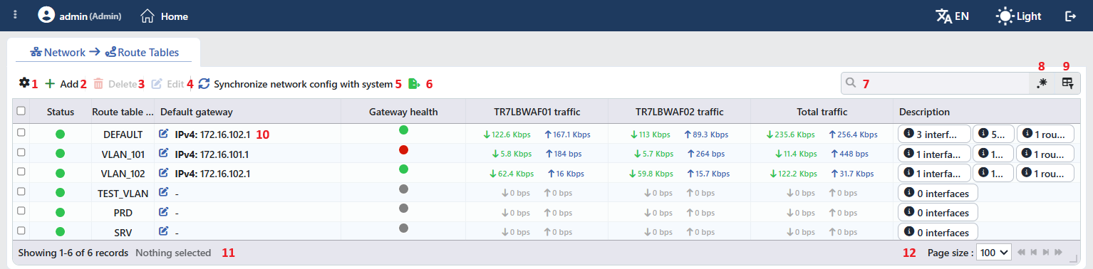 The Route Tables Listing Screen
The table opens with the following columns by default:
| Column | Description |
|---|---|
| Status | The status of the route table in the system is shown with a colored circle; when it is hovered over, the status text appears: 🟢 Up (the table is present in the system), 🔴 Absent in System (the table is present in the configuration but has not been created in the system yet), ⚪ Host Is Down (gray; there is no service connection with the device). In a cluster the circle is split in two; the left half shows this device and the right half the peer device. |
| Route Table Name | The name of the route table. |
| Default Gateway | The default gateways defined in the table are shown in the form IPv4: <address>, IPv6: <address>; if there is no gateway defined, - appears. The pencil icon on the left of the text opens the default gateway form of the table. |
| Gateway Health | The last result of the monitoring profile assigned to the default gateway is shown with a colored circle; when it is hovered over, the status text appears: OK (green), Error (red), Evaluating (orange; the profile and the gateway are defined but there is no decision yet: the first polling is being waited for or the check service does not respond), NO GW/check (gray; no gateway or monitoring profile is defined). In a cluster a separate half circle is shown for every device. The indicator reflects the monitoring of the IPv4 default gateway of the table. |
| Total Traffic | The instant traffic that passes through the route table; the ↓ received and the ↑ sent bandwidth are shown separately and it stays gray while there is no traffic. Sorting and searching cannot be done in this column. |
| Description | The labels that summarize the content of the table: <N> interfaces, <N> IP and <N> routes (the IP and route labels are seen only while the number is greater than zero). |
There is no column hidden by default. The columns take place on the screen in the order above. The table is not sorted by default; when a column header is clicked, first a descending and then an ascending sorting is applied, and at the third click the sorting is removed.
The traffic columns in a cluster setup
While the cluster is enabled, a separate <hostname> traffic column is added for every device before the Total Traffic column (first this device, then the peer device); Total Traffic shows the total of the two devices. These columns cannot be sorted or searched either.
The items in the toolbar are arranged from left to right in the following order; the last two items (Page Information and Page Size) are located in the information strip below the table.
Columns
Which columns will be shown in the table is selected; on this screen all the columns are on by default. In the same panel the columns are reordered by dragging, the alignment is selected per column, in the columns that have been widened by hand there is a Fixed Width badge in order to return to the automatic width and with the Reset button the column layout is returned to the default. The Fit rows to the page button below fits the number of rows to the page. The layout is stored per user.
Add
By clicking the Add button, a new route table creation form is opened in the Add tab. The button is active even while the network configuration is locked.
Delete
When one or more route tables are selected and the Delete button is clicked, the related route tables are deleted; the button is passive while there is no selection and while the network configuration is locked. Before the deletion the "Are you sure that you want to delete route tables object?" confirmation is asked (in a multiple selection "Are you sure you want to delete N route tables objects?").
WARNING
The DEFAULT route table cannot be deleted; if DEFAULT is in the selection, the "Cannot delete default namespace" error is returned without the confirmation window being opened and no table is deleted.
In the confirmation window the side effects of the deletion are listed with their levels; if there is an item at the 🔴 level, a second "This action has destructive consequences. Are you REALLY sure?" confirmation is asked and the confirmation button stays locked for a short time. When any one of the confirmations is cancelled, no operation is done.
| Level | Warning | When it is seen |
|---|---|---|
| 🔴 | "<N> interface(s) in the route table will be deleted: ..." | If there is a non-physical (VLAN, VXLAN, V-ETH, V-ETH(Peer), Bond, LACP, Bridge) interface in the table |
| ℹ️ | "<N> physical interface(s) will move to the default route table: ..." | If there is a physical (ETH) interface in the table; these interfaces are moved to the DEFAULT table |
| 🔴 | "<N> attached interface(s) will also be deleted: ..." | If there are sub-interfaces (VLAN/VXLAN/V-ETH) outside the table that are attached to the interfaces to be deleted |
| 🔴 | "<N> IP address(es) will be deleted: ..." | The IP addresses in the table (including those of the physical interfaces that are moved) |
| 🟠 | "<N> route(s) will be deleted" | The routes in the table |
| ℹ️ | "Member interfaces will be released: ..." / "Bridge member interfaces will be released: ..." / "veth peer interfaces will be left unpaired: ..." | If the members/peers of the Bond/LACP, Bridge or V-ETH(Peer) interfaces to be deleted are being released |
| 🟠 | "The cluster IP pair of the following interfaces will be cleared: ..." | If one of the deleted IPs is the VIP Communication pair of another interface (including a physical interface moved to DEFAULT) |
The name lists in the warnings are shortened with (+N) after six items. When the deletion is confirmed, the IP addresses and the routes in the table and the table itself are removed from the configuration, the physical interfaces are moved to the DEFAULT table and the operation is written to the audit log.
Edit
By clicking the Edit button, the editing form of the selected route table is opened in the Edit tab. The button becomes active only when a single route table is selected. The editing form is the same as the adding form; in addition, a read-only System ID row is displayed and the button of the form becomes Edit. While the tab is open, the preview panel on the right turns into the preview of the form itself, without the header buttons. See Add Route Table › Editing a Route Table.
Synchronize Network Config with System
The Synchronize Network Config with System button synchronizes the network settings in the TR7 configuration with the running system. During the operation the network configuration is locked: the icon of the button turns, and the button and Delete become passive. No separate lock warning is shown on this screen; the lock is understood only from the state of these two buttons.
Export
The table is exported as Excel, CSV or PDF by clicking the Export button. In the window that opens, the Filename, Format and Data Source, together with the Columns to be exported, are determined; the remaining fields are displayed according to the format: CSV Separator for CSV, Excel Sheet Name for Excel, and Page Orientation and Page Size for PDF.
Search
It is used in order to search all the information in the table; the traffic columns are outside the search.
RegExp Search
Used to search all information in the table with a regular expression (RegExp).
Column Based Search
It is used in order to search the information in the table based on the column. Next to the search box of every column there are a negate button that inverts the result and its own RegExp switch; the box of the traffic columns is passive.
Default Gateway
By clicking the pencil icon in the Default Gateway column, the default gateway form of the route table is opened in the Edit Default Gateway (<table name>) tab.
Page Information
Information about the total number of defined route tables and the number of route tables displayed in the list takes place: Showing N-M of T records and the number of selected route tables (N selected, Nothing selected while there is no selection).
Page Size
The maximum number of route tables to be displayed on the page is selected. The default is 100; the options are 5, 10, 20, 50, 100, 200, 500 and All.
Right-Click Menu
When a row is right-clicked, a menu whose header is the name of the route table opens. Both operations in the menu are applied only to the route table that is right-clicked; the selection made in the list does not affect the menu.
| Operation | What it does |
|---|---|
| Edit | Opens the editing form of the route table in the Edit tab; it is the same as the form opened by the Edit button in the toolbar. |
| Delete | Deletes the route table that is right-clicked; the same confirmation flow as the deletion in the toolbar is applied. |
The Preview of the Selected Route Table
When a row is clicked in the list, the preview of the route table opens on the right of the screen; when the selected row is clicked again, the panel closes. In the header there are the status circle of the route table (in a cluster split in two: the left half this device, the right half the peer device), its name and the Route Table subtitle, and at the top right two operations.
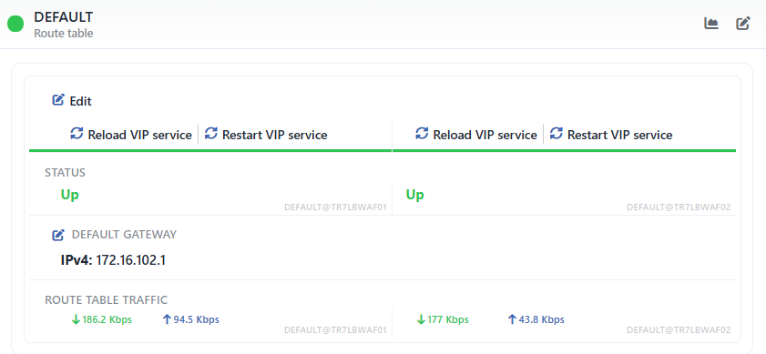 The Preview of the Selected Route Table
| Operation | What it does |
|---|---|
| Dashboard | Opens the dashboard specific to the route table. |
| Edit | Opens the editing form of the route table in the Edit tab; while the tab is open, the panel turns into the preview of the form itself, without the header buttons. |
There is no delete button and no tab in the panel; the deletion is done from the list toolbar or from the right-click menu. At the top of the body there are the operation buttons and below them the information rows; in a cluster every value is shown in two columns (this device and the peer device) with the <table name>@<hostname> label.
The operation buttons in the body are as follows:
| Operation | What it does | Visibility condition |
|---|---|---|
| Edit | Opens the editing tab (the same as the button in the header). | Always |
| Reload VIP Service | Reloads the VIP (VRRP) service in the table on the related device. | In a cluster setup, separately for every device |
| Restart VIP Service | Restarts the VIP (VRRP) service in the table on the related device. | In a cluster setup, separately for every device |
| VTYSH Console | Opens a console window (<hostname> - <zone> - <table name>) connected to the FRR instance of the table; the dynamic routing protocols are configured from here. | If Dynamic Route Table is checked (in a cluster separately for every device) |
| Restart | Restarts the FRR instance of the table. | If Dynamic Route Table is checked (in a cluster separately for every device) |
The information rows in the panel are as follows in order:
| Row | Description | Visibility condition |
|---|---|---|
| Status | The status of the table in the system (Up, Absent in System or Host Is Down); in a cluster it is shown separately for every device. | Always |
| Default Gateway | The IPv4 and IPv6 default gateways defined (IPv4: ..., IPv6: ... or -); the pencil icon next to the label opens the default gateway form. | Always |
| Route Table Traffic | The instant traffic that passes through the route table (↓ received, ↑ sent); in a cluster it is shown separately for every device. | Always |
The Route Tables Dashboard
The Dashboard button in the preview panel opens the dashboard specific to the route table in a separate screen with four tabs:
<table name>: the RRD graph panel. The templates available: Summary, Network, Gateway Check (it is seen only if a gateway monitoring profile is assigned to the table; it shows the gateway status as a timeline), Floods, Connection Limits, Suspicious Packets, Quarantine and Dropped Traffic.- L4 DDoS Management: the L4 DDoS mitigation configuration bound to this route table.
- L4 DDoS Live View: the L4 DDoS live view of the table.
- Quarantine History: the L4 DDoS quarantine history of the table.
While the first tab is open, the preview panel is seen on the right again; in this panel there is only the Edit button and it opens the editing form of the table as a closable Edit tab on this screen. When the DDoS tabs are passed to, the preview panel closes.
The Route Tables Adding Form
A new route table is added on the TR7 device by following the Network → Route Tables → Add steps.
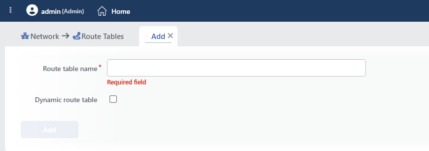 The Add Tab
INFO
Route Table Name Required
A unique name is entered for the route table (1–15 characters; required). When it is left empty, the "Required field" warning, for a long name the "Route table name must have 1-15 characters" warning, and for a name that is in use the "Name is used" warning is given. A format that reflects the purpose of use is recommended in the naming (e.g. RT_DMZ, RT_CUSTOMER_A, RT_INTERNAL). The name can be edited after it is created; the internal identity (id) of the table and the table number are independent of the name.
INFO
Dynamic Route Table Default: Unchecked
Whether the dynamic routing protocols will be run on the route table is determined (a check box, unchecked by default). In TR7 dynamic routing is provided over the FRRouting (FRR) infrastructure; when the option is checked, the FRR Mode and the daemon switches become visible in the form; after the record a separate FRR instance is run for the table.
FRR Mode
It determines the FRR configuration profile for all the dynamic routing daemons in the route table; TR7 passes the selected profile directly to FRR (frr_profile). The timer and behavior differences are applied not by TR7 but by the profile semantics of FRR itself. Two options are offered in the list in lower case (the default is traditional):
- traditional: the classic/conservative default profile of FRR; it is a general purpose profile compatible with traditional and enterprise network environments. Default.
- datacenter: the profile of FRR tuned for data center / CLOS fabric environments; it enables the default behavior and timers suitable for these environments.
The Daemons
When dynamic routing is enabled, one or several of the daemons below can be turned on. Every daemon is an Enabled / Disabled switch (the default is Disabled); when it is turned on, the related FRR start options are entered in the box next to it. The default option is -A 127.0.0.1; for the IPv6 daemons OSPF6D and RIPNGD it is -A ::1. The option text is not validated and is passed to FRR as it is.
| Daemon | Area of Use |
|---|---|
| BGPD | Border Gateway Protocol; ISP connections, routing between large networks |
| OSPFD | Open Shortest Path First; enterprise internal network routing (IPv4) |
| OSPF6D | OSPFv3; OSPF for IPv6 environments |
| RIPD | Routing Information Protocol; simple routing in small networks (IPv4) |
| RIPNGD | RIP Next Generation; RIP for IPv6 |
| ISISD | Intermediate System to Intermediate System; link-state routing, large-scale SP networks |
| PIMD | Protocol Independent Multicast; multicast routing |
| LDPD | Label Distribution Protocol; MPLS label distribution |
| NHRPD | Next Hop Resolution Protocol; DMVPN/NBMA address resolution |
| EIGRPD | Enhanced Interior Gateway Routing Protocol; compatibility with Cisco environments |
| BABELD | Babel; distance-vector routing for wireless/mesh networks |
| SHARPD | Super Happy Advanced Routing Process; a helper daemon for route injection/testing |
| PBRD | Policy-Based Routing; policy-based routing |
| BFDD | Bidirectional Forwarding Detection; fast link failure detection |
| FABRICD | OpenFabric; data center fabric routing |
| VRRPD | Virtual Router Redundancy Protocol; gateway redundancy |
| PATHD | Segment Routing Traffic Engineering (PCEP); path computation |
TIP
The selection of the dynamic routing protocol depends on the network topology and on the existing infrastructure. In enterprise internal networks usually OSPFD, and in ISP connections BGPD is preferred. The protocol configuration of the selected daemons is done, after the table is created, over the VTYSH Console opened from the preview panel.
For the differences in a cluster setup see the Add Route Table (Cluster) page.
The Default Gateway Form (Edit Default Gateway)
When the pencil icon in the Default Gateway column or the pencil icon next to the Default Gateway row in the preview panel is clicked, the default gateway form of the route table is opened in a closable tab titled Edit Default Gateway (<table name>). The form manages the routes destined for 0.0.0.0/0 (::/0 for IPv6) in the table from a single place; the same routes can also be edited row by row with the Default Gateway option in the Add Static Routing form and are seen in the route list with the IPv4 default gateway (<table name>) / IPv6 default gateway (<table name>) label.
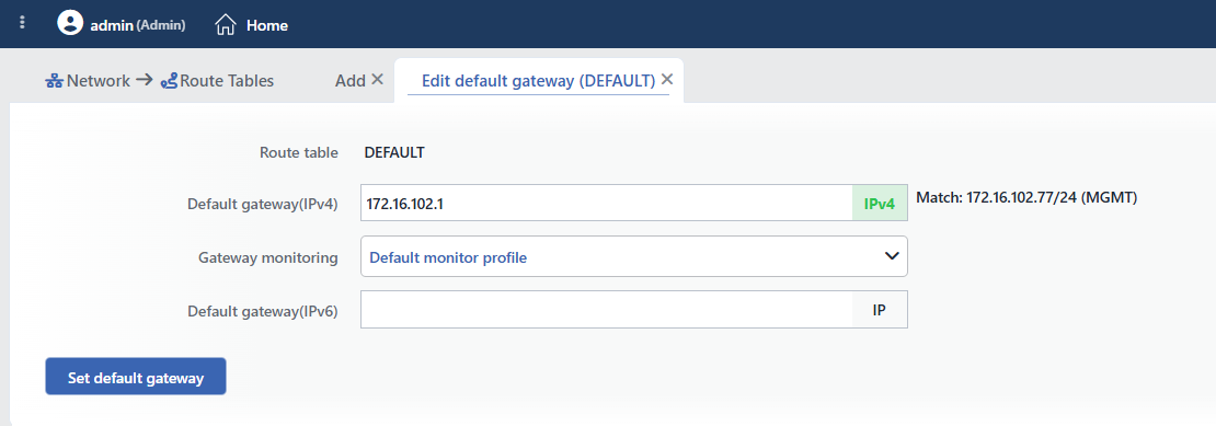 The Edit Default Gateway Tab
INFO
Route Table
The name of the route table being edited; it is for information only and cannot be changed.
INFO
Default Gateway(IPv4)
The IPv4 default gateway address of the table; it is not required and does not accept a CIDR or a port. When a valid IPv4 address is entered, the table IP in the same subnet as the gateway is shown below the field in the form "Match: <ip>/<cidr> (<interface name>)". When the field is left empty and the form is saved, the existing IPv4 default gateway is deleted.
INFO
Gateway Monitoring
The health check profile that will check the reachability of the default gateway. In the list there are No Check (no check), Default Monitor Profile (the system-defined Ping profile) and all the health check profiles of the Ping type with their names; the profiles of the other types are not listed. The field is prefilled with the current monitoring profile of the table.
TIP
The monitoring profile is stored bound to the gateway route record and is reflected to the Gateway Health column from here. In order to assign a profile, use the Gateway Monitoring field that opens with the Default Gateway option in the Add Static Routing form; the selection in this form is not written to the route record.
INFO
Default Gateway(IPv6)
The IPv6 default gateway address of the table; it works in the same way as the IPv4 field and shows its own "Match: ..." tooltip. When it is left empty, the existing IPv6 default gateway is deleted.
INFO
Set Default Gateway
The Set Default Gateway button saves the form without confirmation being asked; while there is an erroneous field in the form, the button is passive. In the record, for every IP version:
- The first interface that has an IP in the same subnet as the gateway entered is selected automatically; the interface is not selected by hand. If there is no matching IP in the table, the "No network matches default gateway
<gw>(IPv<v>)" error is returned and no change is applied. - If there is no default gateway for that version in the table, a new route is created; if there is one and the new gateway falls on a different interface, the old route is deleted and the new one is added; if it is on the same interface, only the gateway address is updated. For a gateway that is moved to a different interface the new route is created without a monitoring profile; if a profile is required, it must be assigned again from the Add Static Routing form.
- If the field is empty, the default gateway route of that version is deleted.
The changes are reflected to the route list immediately; in order for them to be applied to the running system, synchronization is required as for the other network changes.
Usage Location
The route table created is used in the following places:
- It is selected in the Route Table field in the Edit Interface form and the interfaces are moved to the table.
- New virtual interfaces are created directly in this table in the Add Interface form.
- It is seen as the route table filter in the Add IP Address and Add Static Routing forms.
- It is selected in the Route Table fields in the Backend Service and vService forms.
- The Firewall rules are defined per route table; every table has its own rule set.