
Smarter by Design.Simpler for Business
Interfaces List (Standalone)
What Is Interfaces List?
Interfaces List are the physical or virtual connection points that allow the TR7 device to communicate with the network. Each interface forms the fundamental building block for IP addresses, routing rules and the network configuration.
In the TR7 architecture, network management is designed around the Route Table. This structure allows isolated virtual routing domains (VRF-like) to be created on the same device and different network segments to be managed independently.
The Interfaces screen is the central management point for all the network interfaces defined on the TR7 device. From this screen:
- The status of physical and virtual interfaces is monitored,
- IP address assignments are made,
- Static routing rules are defined,
- Route tables are created and managed,
- The network topology is reviewed visually.
Standalone / Cluster
This page describes the screen that is seen while clustering (cluster) is disabled. In clustering the same screen extends with the IP column being shown separately for both devices, two-colored status indicators and VIP rows; see Interfaces (Cluster).
8 Interface Types
Flexible structure
ETH · VLAN · VXLAN · V-ETH · V-ETH(Peer) · Bond · LACP · Bridge
Route Table
Network isolation
VRF-like, multi-tenancy
Status Monitoring
Color-coded
Up · No link · Down · Absent
Topology
Visual map
Hierarchical interface view
Why Is Interfaces List Important?
In modern data center environments, network interfaces are not merely physical connection points; they are the fundamental building blocks of traffic management, security isolation and high availability architectures.
Correctly configuring network interfaces on TR7 has a direct impact on load balancing performance, firewall effectiveness and overall system stability. A misconfigured interface can lead to traffic interruptions, security holes or performance problems.
TR7's route table based network architecture offers flexibility beyond traditional network configurations:
- Multi-Tenancy: Secure multi-tenant architectures can be built by fully isolating different customers' traffic from one another on the same physical device,
- Traffic Segmentation: Management, production and test traffic can be separated into different route tables to provide security and performance isolation,
- VRF-Like Configurations: Each route table can have its own routing rules and DNS configuration,
- Flexible Interface Types: Complex network topologies are supported through various virtual interface types such as VLAN, LACP, Bond and Bridge.
Thanks to correctly configured network interfaces, service interruptions are minimized, firewall and load balancing policies are enforced effectively, network traffic can be monitored and rapid intervention is possible in maintenance/failure scenarios.
Supported Interface Types
TR7 supports various interface types to meet different network requirements. Each type is optimized for specific scenarios.
| Type | Description | Use Case |
|---|---|---|
| ETH | Physical Ethernet interfaces. Interfaces that exist physically on the device or are assigned in a virtualization environment | Basic network connectivity, management access |
| VLAN | IEEE 802.1Q VLAN interfaces. Creates logical segments on a physical interface (ID: 2–4094) | Network segmentation, traffic isolation |
| VXLAN | VXLAN (Virtual Extensible LAN) overlay interface; it tunnels a Layer-2 network over Layer-3 | Overlay networks, L2 extension between locations |
| V-ETH | Virtual Ethernet interfaces (macvtap). A virtual interface with an independent MAC address on a physical interface | Container/VM connectivity, network virtualization |
| V-ETH(Peer) | Virtual Ethernet pair. A two-ended virtual interface connection | Communication between route tables |
| Bond | A bonding interface that combines multiple physical interfaces (Balance-rr / round-robin) | Bandwidth, simple load distribution |
| LACP | IEEE 802.3ad Link Aggregation. Dynamic load balancing and redundancy | High bandwidth, active-active redundancy |
| Bridge | Software network bridge. Connects multiple interfaces to the same Layer-2 domain | Transparent bridging, VM networking |
Attention
ETH (physical) interfaces cannot be deleted through the TR7 interface. These interfaces depend on the device's hardware or virtualization environment.
Virtual interface hierarchy: VLAN interfaces can only be created on top of physical (ETH), Bond or LACP interfaces; V-ETH (macvtap) interfaces can be created on top of ETH, VLAN, Bond or LACP. Bond and LACP combine multiple physical interfaces in a single logical interface; for LACP the LACPDU transmission rate can be set as fast (1 sec) or slow (30 sec).
Interface and IP Statuses
On the Interfaces screen the status indicators make the network connection status instantly visible with color codes. These indicators are of critical importance for operational monitoring and troubleshooting.
Interface Connection Statuses
Up · greenThe interface is active and a physical connection (carrier) is present.
No link · yellowThe interface is up but there is no physical connection (carrier); the cable is unplugged, the other side is off, etc.
Down · grayThe interface has been shut down administratively (down).
Absent in system · redThe interface is not present in the system.
IP Address Statuses
Up · greenThe IP address is active and usable.
No link · yellowThere is no physical connection (carrier) on the interface the IP is bound to.
Down · grayThe IP or the interface it is bound to is down or is not present in the system.
Absent in system · redThe interface the IP is bound to is not present in the system.
Disabled · light grayThe IP address has been disabled by the user (it is shown dimmed/struck through).
Route Statuses
Route active · green dotThe route has been applied to the system and is active.
Gateway reachableThe default gateway monitoring is successful; the ✓ check mark is shown.
Gateway unreachableThe gateway monitoring has failed; the ✕ mark is shown.
The gateway indicator appears only in the row of a default gateway on which a gateway monitor profile is defined: ✓ (successful), ✕ (failed), orange while the evaluation continues and gray when no result has been recorded yet. It is not displayed in the other routes.
When the status icons are hovered over, the status information is displayed as a tooltip. In a cluster setup the status of both devices is shown separately for every interface/IP and the device name is added to the tooltip as well.
The Route Table Concept
TR7 can create network environments on the same device that are completely isolated from one another. Each route table can have;
- Its own interface assignments,
- Its own IP addresses,
- Its own routing tables,
- Its own DNS configuration,
- Optional dynamic routing protocols (BGP, OSPF, RIP, etc.)
associated with it.
The Default Route Table (DEFAULT): All the physical interfaces are initially assigned to the DEFAULT route table. When no additional route table is created, all the network traffic is managed through this table.
Multiple Route Table Scenarios:
- Customer Isolation (Multi-Tenancy): Isolating different customers' traffic from one another,
- Traffic Separation: Running management and production traffic in different network domains,
- VRF Configuration: Creating virtual routing and forwarding instances,
- Test Environments: Running test and production environments in isolation on the same device.
If more than one route table is defined, the interfaces in a specific table can be displayed with the Route Table filter on the listing screen. For detailed information about creating and managing route tables see the Route Tables page.
The Network Topology View
The Network Topology feature visually presents the hierarchical relationships between the interfaces. Thanks to this view;
- Which virtual interfaces (VLAN, LACP, V-ETH, etc.) are created on top of which physical interface,
- The dependencies between the interfaces,
- The members of the Bond or LACP groups,
- The interfaces attached to a Bridge
can easily be understood. In the topology diagram the interface types are shown with icons and filtering can be done according to the route table. In complex network configurations the topology view makes it easier to detect configuration errors and to verify the network architecture.
Technical Limits and Rules
The technical limits that apply when creating interfaces and sub-components:
| Parameter | Value / Rule |
|---|---|
| Interface name | 1 – 15 characters; it starts with a letter or a digit and can then contain a–z, 0–9, _, . and - (case-insensitive; the validation rule in the interface adding form) |
| VLAN ID | 2 – 4094 |
| MTU | No lower/upper limit is enforced in the form; the common value 1500 is used, 9000 for jumbo frames |
| LACP transmission rate | fast (1 sec) or slow (30 sec) |
| VLAN parent interface | ETH, Bond or LACP |
| V-ETH parent interface | ETH, VLAN, Bond or LACP |
How to View?
The following steps are followed in order to list and examine the network interfaces defined on the TR7 device:
- The Configuration Menu is opened by clicking the TR7 logo at the bottom left.
- The Network → Interfaces steps are followed.
- On the screen that opens, all the interfaces defined on the device are listed in table format.
- By selecting an interface from the list, the details, IP addresses, routes and operation records of that interface are displayed in the preview panel on the right.
TIP
Reaching the page via quick search
Instead of navigating the menu step by step, the related page is reached directly by using the search bar in the bottom left corner of the screen. The search bar opens with the Alt + T shortcut on Windows and Opt + T on macOS; typing the name of the feature being searched for is then sufficient.
For the interfaces that belong to different route tables the Route Table filter, and in order to see the hierarchical structure between the interfaces the Network Topology view, can be used.
Best Practices
- Synchronize the network after a change. After making interface, IP or route changes, synchronize the configuration with the system with Actions → Synchronize Network Config with System; the disappearance of the "Network is under action. Please wait..." warning in the toolbar shows that the operation has been completed.
- Manage the management interface carefully. Making the management interface (usually MGMT) or an interface that carries active traffic Down may cause access to the device to be cut off. Before shutting an interface down, check the IP addresses and the routes on it.
- Verify the structure with the network topology. After adding virtual interfaces such as VLAN, LACP or Bridge, check from the Network Topology view that the hierarchical structure has been formed correctly.
- Use the route table filter. In environments where more than one route table is defined, use the Route Table filter in order to see only the interfaces in the related table.
- Disabling an IP address vs. deleting it. In order to take an IP address out of use temporarily, use Disable (the configuration is preserved and it can be enabled again); Delete removes the configuration completely.
- Monitor the interface statistics regularly. Open the historical view with Stats by right-clicking the route table cell; for the interface-based dashboard, the Dashboard of the related interface can be reached from the Interfaces tab on the Left Monitor Panel. Abnormal traffic patterns, packet losses or increases in the error counters may point to network problems.
The Interfaces List Screen
The list of all the interfaces defined on the TR7 device is reached by following the Network → Interfaces path. The screen consists of the (A) listing area in which the interfaces are listed and the (B) preview panel in which the details of the selected interface are displayed; the operations of adding, editing and deleting an interface, an IP address and a route are done from this screen.
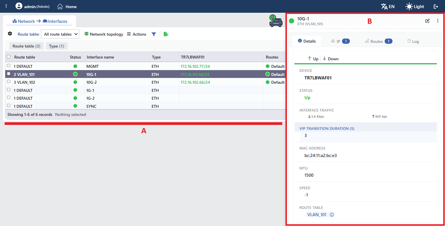 The Interfaces List Screen (A: the list, B: the preview)
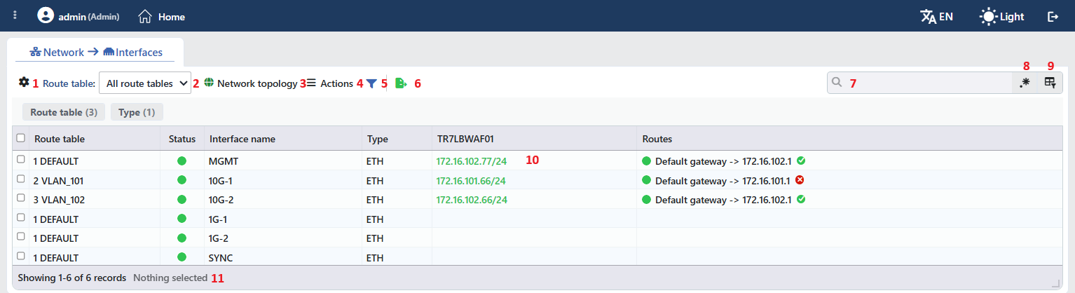 The Listing Area and the Toolbar
The table opens with the following columns by default:
| Column | Description |
|---|---|
| Route Table | The route table the interface is bound to (in the form 1 DEFAULT). While there is a single route table on the device, this column is not seen. |
| Status | The status indicator of the interface. |
| Interface Name | The name of the interface. |
| Type | The interface type (ETH, VLAN, VXLAN, V-ETH, V-ETH(Peer), Bond, LACP, Bridge). |
| The device name | The header of the column is the Server Name value of the device; the IP addresses assigned to the interface are listed as sub-rows with the status colors. |
| Routes | The routes defined on the interface as sub-rows in the form destination/CIDR -> gateway; if a monitor is defined on the default gateway, there is a ✓/✕ indicator next to it. |
The following column is hidden by default and is added from the column selector:
| Column | Description |
|---|---|
| IP Description | The descriptions of the IP addresses assigned to the interface. |
The IPs and the routes of an interface are not split into separate rows; they are stacked as sub-rows inside the interface row. The list is offered on a single page without pagination. In narrow windows the Route Table, Type and Routes columns can be hidden automatically in order to make room.
The items in the toolbar are arranged from left to right in the following order; item number 10 is the IP address cell in the table and the last item (Page Information) is located in the information strip below the table.
Columns
Which columns will be shown in the table is selected; the columns other than IP Description are on by default. In the same panel the columns are reordered by dragging and the alignment is selected per column; with the Fit rows to the page button the row height is fitted to the page and with the Reset button the column layout is returned to the default. The layout is stored per user.
Route Table
It is used in order to filter the interfaces in a specific route table. All Route Tables is selected by default. This filter is seen only when more than one route table is defined. For detailed information see the Route Tables page.
Network Topology
It opens the hierarchical topology view of the interfaces in the Network Topology tab. The physical interfaces and the virtual interfaces created on them (VLAN, LACP, etc.) are shown visually; at the top right, filtering based on the route table can be done.
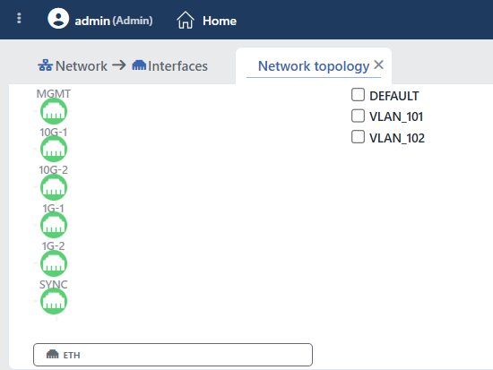 Network Topology
Actions
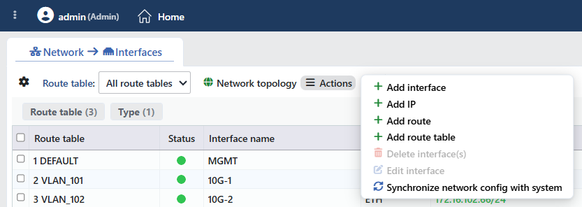 Actions
The Actions button opens the operation menu for interface management; the forms in the menu open in separate tabs on the same screen:
| Operation | Description |
|---|---|
| Add Interface | Opens the new interface adding form → Add Interface |
| Add IP | Opens the IP address adding form → Add IP Address |
| Add Route | Opens the static routing adding form → Add Static Routing |
| Add Route Table | Opens the new route table creation form → Add Route Table |
| Delete Interface(s) | Deletes the selected interface(s); it is passive while there is no selection (physical ETH interfaces cannot be deleted) |
| Edit Interface | Opens the editing form of the selected interface; it is active only while a single row is selected → Edit Interface |
| Synchronize Network Config with System | Synchronizes the network configuration with the operating system |
Synchronization: When Synchronize Network Config with System is selected, the network settings in the TR7 configuration are synchronized with the operating system. While the synchronization continues, the Syncing Network... progress indicator and, when it is completed, All synced is displayed in the status bar of the interface (next to the WEB-CLI button).
WARNING
While a network operation continues, the "Network is under action. Please wait..." warning is seen in the toolbar; until the operation is completed, the delete, edit and synchronize options in the Actions menu and the IP/route adding options in the right-click menu stay passive.
 Synchronization - 1
 Synchronization - 2
Filter
The Filter button is used in order to filter the interfaces shown in the list according to certain criteria; the button shows the number of active filters with a badge. The strip comes open by default and contains two cards: Route Table (only while there is more than one route table) and Type (the interface type). In the card header there are the filter name and the number of values; when the card is clicked, the values are listed below it with their row counts.
Export
The table is exported as Excel, CSV or PDF by clicking the Export button. In the window that opens, the Filename, Format and Data Source, together with the Columns to be exported, are determined; the remaining fields are displayed according to the format: CSV Separator for CSV, Excel Sheet Name for Excel, and Page Orientation and Page Size for PDF.
Search
Used to search all information in the table.
RegExp Search
Used to search all information in the table with a regular expression (RegExp).
Column Based Search
Used to perform a column-based search on the information in the table.
Display of Interface and IP Addresses
The statuses of the interfaces and the IP addresses are shown with color codes (Up / No link / Down / Absent; disabled IPs are dimmed and struck through). For the details see the Interface and IP Statuses section. When the status icon is hovered over, detailed information is displayed as a tooltip; with the copy icon that appears when the IP is hovered over, the address can be copied to the clipboard.
Page Information
Information about the total number of defined interfaces and the number of interfaces displayed in the list takes place: Showing N-M of T records and the number of selected interfaces (N selected, Nothing selected while there is no selection). The list is offered on a single page without pagination; there is no Page Size selector on this screen.
Right-Click Menu
When the interface row, the IP address, the route or the route table cell is right-clicked in the listing table, an operation menu that belongs to that object opens. The operations are applied only to the object that is right-clicked; the selection made in the list does not affect the menu.
Right-Clicking an Interface
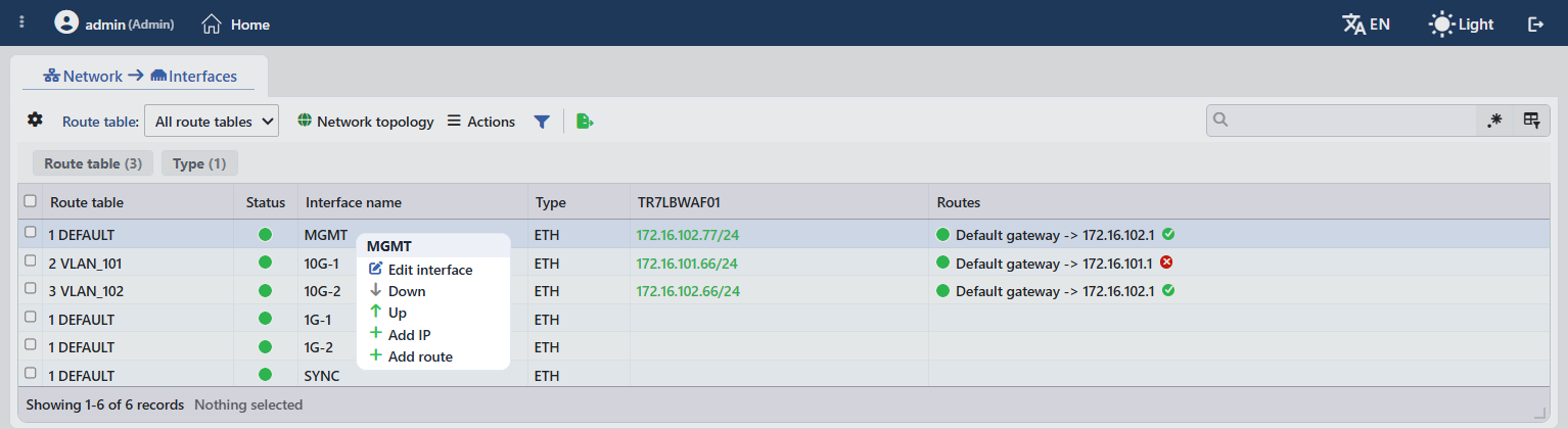 Right-Clicking an Interface
In the menu header there is the name of the interface.
| Operation | What it does |
|---|---|
| Edit Interface | Opens the interface editing form |
| Down | Disables the interface |
| Up | Puts the interface into service |
| Add IP | Adds an IP address to the interface |
| Add Route | Adds a static route to the interface |
On an interface that is a Bond/LACP member, Add IP and Add Route are passive.
Right-Clicking an IP Address
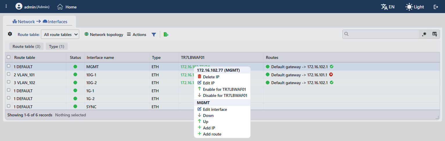 Right-Clicking an IP Address
In the menu header there are the IP address and the interface name (in the form ip (interface)).
| Operation | What it does |
|---|---|
| Delete IP | Deletes the IP address |
| Edit IP | Opens the IP address editing form |
| Enable for [Hostname] | Enables the IP address |
| Disable for [Hostname] | Disables the IP address |
In the lower part of the menu, in the second group whose header is the name of the interface, all the operations in the interface menu (Edit Interface, Down, Up, Add IP, Add Route) take place.
Right-Clicking a Route
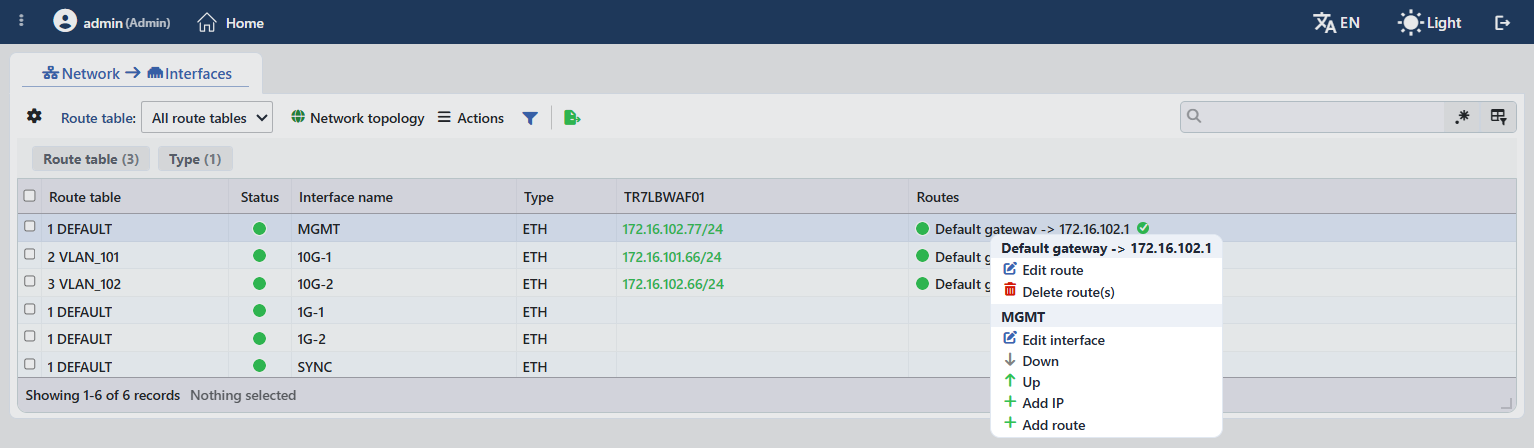 Right-Clicking a Route
In the header of the menu that opens when a static route or the default gateway is right-clicked there is the route (in the form Default gateway -> 172.16.102.1):
| Operation | What it does |
|---|---|
| Edit Route | Opens the route editing form |
| Delete Route(s) | Deletes the route |
In the lower part of the menu, in the second group whose header is the name of the interface, all the operations in the interface menu (Edit Interface, Down, Up, Add IP, Add Route) take place.
Right-Clicking a Route Table
When the cell in the Route Table column is right-clicked, the operations for the related route table are listed:
| Operation | What it does |
|---|---|
| Edit | Opens the route table editing form |
| Delete | Deletes the route table (the DEFAULT table cannot be deleted) |
| Stats | Opens the historical view of the route table in a closable tab |
The Preview of the Selected Interface
When a row is clicked in the list, the preview of the interface opens on the right of the screen. When the panel is closed, it is opened again with the handle with the tool icon that carries the status color of the interface, at the top right of the listing area.
In the header of the panel there are the name of the interface; below it the description that summarizes its type and its bonds (e.g. ETH (DEFAULT), VLAN100@eth0, BOND[eth1,eth2], V-ETH@eth0; if there is more than one route table, the table name is added as well: VLAN100@eth0 (DEFAULT)) and the status indicator.
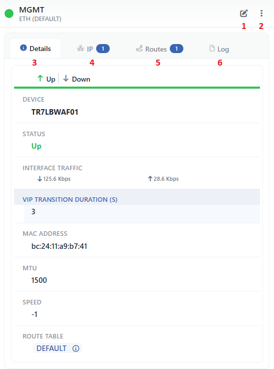 The Preview of the Selected Interface
In the header of the panel there are two operations and below it the tabs; in the header of the IP and Routes tabs the number of related records is shown as a badge.
Edit Interface
It is the pencil icon at the top right of the header; it opens the Edit Interface form of the selected interface in the Edit Interface tab.
The Actions Menu
It is the ⋮ menu next to the pencil icon. Inside it there are the Delete Interface, Up and Down operations.
Details
At the top of the panel there are the two buttons that turn the interface on and off, and below them the technical information of the interface:
| Operation | What it does |
|---|---|
| Up | Puts the interface into service (turns it on). |
| Down | Disables the interface (turns it off). |
The rows in the tab are as follows in order:
| Row | Description | Visibility condition |
|---|---|---|
| Device | The TR7 device name (hostname). | Always |
| Status | The instant status of the interface (Up, Down, No Link, Absent in System, etc.). | Always |
| Interface Traffic | The instant incoming (↓) and outgoing (↑) traffic. | Always |
| VIP Transition Duration (s) | The VRRP advertisement interval to be used when clustering is passed to. | Always (in a standalone setup as well) |
| MAC Address | The MAC address (it is read from the live system information). | Always |
| MTU | The Maximum Transmission Unit value. | Always |
| Speed | The connection speed (1 Gbps, 10 Gbps, etc.); -1 in the interfaces whose speed cannot be read. | Always |
| Description | The description of the interface. | If a description is defined |
| Route Table | The route table the interface belongs to; the information icon next to it opens the details of the table. | Always |
IP
The IP addresses assigned to the interface (the IP/CIDR value and the status indicator) are listed. In the toolbar of the tab there is the Add IP button; the other operations that depend on the selection are gathered in the Actions menu:
| Operation | What it does |
|---|---|
| Add IP | Adds a new IP address → Add IP Address |
| Delete IP | Deletes the selected IP address |
| Edit IP | Opens the editing form of the selected IP address |
| Enable for [Hostname] | Enables the selected IP address |
| Disable for [Hostname] | Disables the selected IP address |
The same operations can be reached by right-clicking the rows. On an interface that is a Bond/LACP member, Add IP is passive.
Routes
The static routes defined on the interface are listed with the Status, Destination Network (CIDR) and Gateway columns; if a monitor is defined on the default gateway, the ✓/✕ next to it shows the reachability. In the toolbar of the tab there is the Add Route button; the other operations that depend on the selection are gathered in the Actions menu:
| Operation | What it does |
|---|---|
| Add Route | Adds a new static route → Add Static Routing |
| Delete Route(s) | Deletes the selected route(s) |
| Edit Route | Opens the editing form of the selected route |
The Network Topology tab is conditional
If the interface has a hierarchical bond with other interfaces (if a VLAN/V-ETH is defined on it, if it is a member of a bond or a bridge, etc.), a Network Topology tab is also added to the tab strip between Routes and Log; it shows the topology of the interface itself. On the interfaces that have no such bond this tab is never displayed, and for this reason it is not seen in the image above either.
Log
It lists the user operations on the interface (adding, editing, deleting) as a timeline.
Delete Confirmations and Protection Mechanisms
The delete and edit operations on network objects are not applied blindly; before running the operation, TR7 calculates its side effects and lists them in the confirmation window.
Confirmation with an impact preview
- The delete operations always ask for confirmation; in the confirmation window the side effects of the operation are listed marked according to their level of importance: 🔴 destructive, 🟠 warning, ℹ️ information. Examples: "${count} attached interface(s) will also be deleted" (the attached virtual interfaces), "${count} IP address(es) will be deleted", "Route table '${name}' will lose its IPv${v} default gateway".
- If there is an item at the 🔴 level in the list, a second confirmation window opens: "This action has destructive consequences. Are you REALLY sure?"; in order to prevent confirming by mistake, the confirmation button stays locked for a short time.
- In the edit operations confirmation is asked only if there is a side effect; the adding operations are applied without confirmation.
Protected objects
- Physical (ETH) interfaces cannot be deleted. They can be moved to a different route table; if their table is deleted, they are moved automatically to the DEFAULT table.
- The DEFAULT route table cannot be deleted.
- The IP addresses used in the management access lists (HTTP, HTTPS, SSH, SNMP) of the device are protected; when an attempt is made to delete them, the "${ip} is protected. (${reason})" error is returned and the interface that carries this IP is taken under protection as well.
- Bond/LACP member interfaces cannot have an IP or a route added to them.