
Smarter by Design.Simpler for Business
TR7Enterprise Application Delivery & Security Platform
Two Arm Topology - Routed Backend is the deployment in which the server arm of Two Arm Topology is a transit network (all vService addresses in a single publishing network; on the server side, a separate network dedicated only to TR7 that contains no servers; the Backend Services are in different networks behind this network, and TR7 reaches them through routing). TR7 does not connect directly to any server network; it reaches all of them from a single arm, through the network's routing point.
No matter how many separate networks the servers are spread across, the number of connections on the TR7 side does not change: one publishing arm, one transit arm. When a new server network is added, TR7 is not given a new interface or address; defining the path to that network is enough. This is the natural deployment for data centers that have many server networks and in which routing is gathered at a central point.
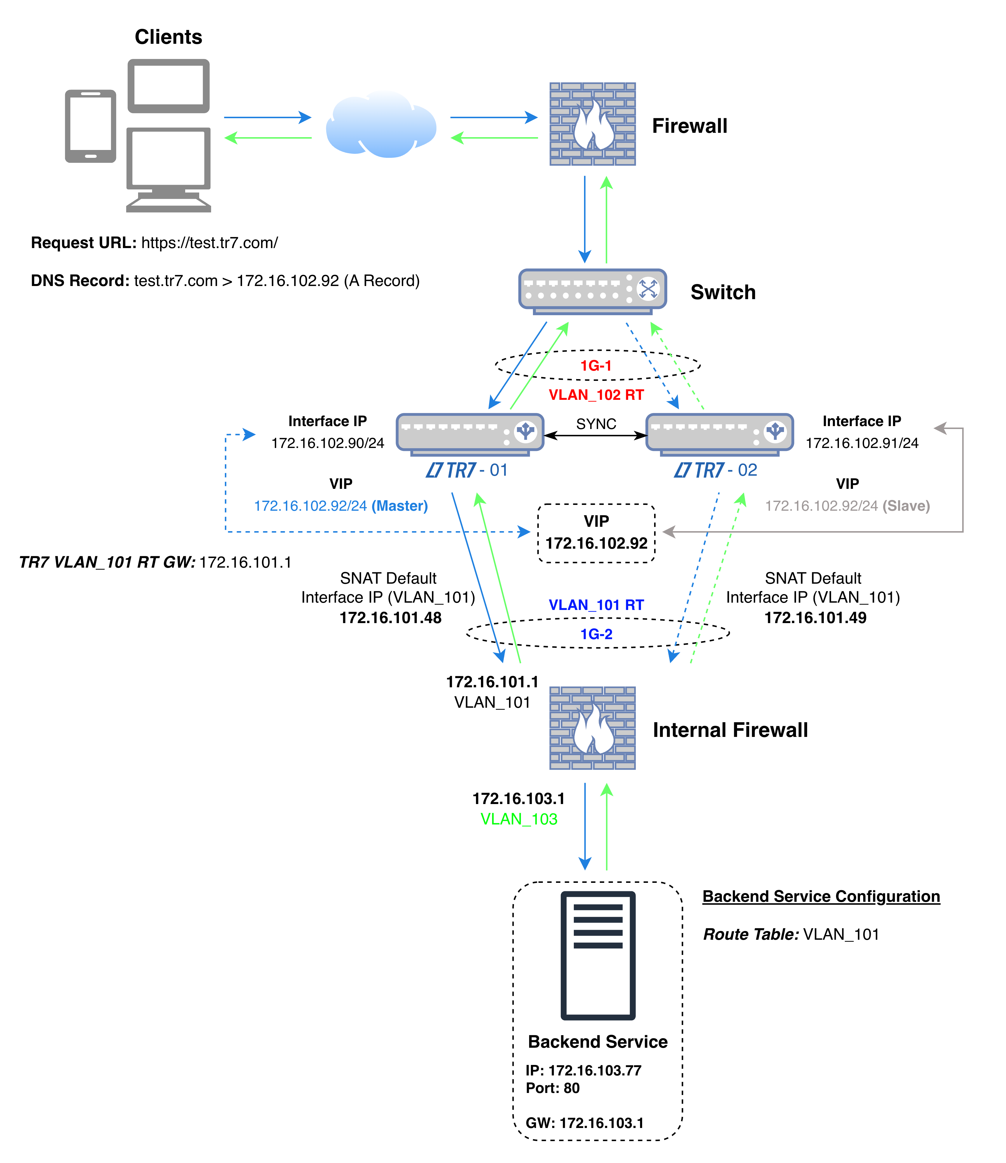 Two Arm Topology - Routed Backend
The diagram shows the flow of traffic: the VIP the client connects to is on the interface in the publishing network (1G-1, VLAN_102 in the diagram), while the address TR7 uses when connecting to the Backend Service is on the second interface in the transit network (1G-2, VLAN_101 in the diagram). The Backend Service is in a different network (VLAN_103) behind the routing point (Internal Firewall in the diagram); TR7 has no interface in this network.
In the diagram's example, on the Internal Firewall, access is allowed from the addresses 172.16.101.48 and 172.16.101.49, which the TR7 devices use when connecting to the Backend Service, to the address and port of the Backend Service (172.16.103.77:80). Both the application traffic and the health check are made from these addresses; the Backend Service sees these addresses as the source of the connection and returns the response to TR7 over the same path. For the health check, this applies while the Health Check Source IP field in the Backend Service is at its default value; when another address is selected in the field, the check is made from that address.
In the diagram's example, the source and destination information of the packets in the four steps of the connection is as follows (while TR7-01 is the active device):
| Step | Direction | Source IP | Source Port | Destination IP | Destination Port |
|---|---|---|---|---|---|
| 1 | Client → TR7 | Client IP | Random | 172.16.102.92 (VIP) | 443 |
| 2 | TR7 → Backend Service | 172.16.101.48 (Interface IP) | Random | 172.16.103.77 | 80 |
| 3 | Backend Service → TR7 | 172.16.103.77 | 80 | 172.16.101.48 (Interface IP) | Source port of step 2 |
| 4 | TR7 → Client | 172.16.102.92 (VIP) | 443 | Client IP | Source port of step 1 |
| Color | Meaning |
|---|---|
| Request | |
| Response |
When the VIP moves to the other device, the TR7 address in steps 2 and 3 becomes 172.16.101.49.
| A separate arm for each server network | With Routed Backend |
|---|---|
| An interface or VLAN and an address from that network are defined on TR7 for each server network. | On TR7, there is a single arm and a single network for the server side. |
| A new server network means a new interface and address on TR7. | A new server network is brought into scope when the Backend Service's route table has a path to that network. |
| Access rules between server networks are managed at more than one point. | The traffic going from TR7 to the servers passes through the network's routing point and is managed by the rules there. |
| TR7 is a member of each server network. | TR7 stays outside the server networks; the servers know it only by its address in the transit network. |
Since the server sends its response to TR7's address, the return path is provided by the network's ordinary routing: no additional routing rule or address translation is needed for the return traffic.
If the applications are spread across different VLANs and networks, TR7 reaches all of them over a single transit arm, instead of connecting to each of them separately.
If traffic between networks is to pass through a core switch or firewall, the traffic TR7 sends to the servers also passes through the same point.
As new server networks are added, TR7's interface and address configuration stays the same; the publishing network and the transit network are preserved as two fixed points.
Requirements of this deployment
How does the client IP address appear on the server?
In this deployment, the Backend Service sees TR7's address in the transit network as the source of the connection. The real client address is forwarded with the X-Forwarded-For header on HTTP vServices, and with Proxy Protocol on HTTP and L7 TCP vServices where the Backend Service supports it; both options are disabled by default.